


Abstract: If you’ve ever wondered what terms like module, pitch diameter, pressure angle, backlash, contact ratio, or involute profile actually mean, this guide is for you. Gear terminology is more than a collection of definitions—it is the common engineering language used to design, manufacture, inspect, and troubleshoot gear systems.
In this comprehensive guide, you’ll learn over 50 essential gear terms, understand how they relate to gear geometry and tooth design, explore key calculations and industry standards, and see how these concepts influence gear performance in real applications. From basic tooth anatomy to manufacturing processes and quality inspection, this article serves as a complete reference for engineers, designers, buyers, and anyone working with gears.
Understanding Gear Terminology
Every gear, regardless of its type or application, is described using a standardized set of engineering terms. These terms define a gear’s geometry, tooth profile, dimensions, meshing characteristics, and performance parameters. With them, engineers, manufacturers, and buyers can communicate with precision throughout the entire product lifecycle.
Today, gear terminology is standardized by international organizations such as ISO, AGMA, and DIN, providing a common engineering language used worldwide.
This guide is designed for:
- Mechanical engineers designing transmission systems
- Gear designers calculating gear geometry and tooth proportions
- Manufacturing engineers producing precision gears
- Quality inspectors verifying gear dimensions and accuracy
- Purchasing engineers evaluating supplier specifications
- Students and beginners building a solid foundation in gear design
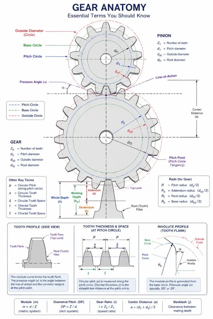
Gear Anatomy Overview
Before exploring individual terms, it’s helpful to understand where each feature is located on a gear. Most terminology refers to one of four aspects of gear design:
- Basic geometry– pitch circle, base circle, outside diameter, root diameter, and center distance.
- Gear tooth anatomy– tooth face, flank, tip, root, addendum, dedendum, and tooth thickness.
- Meshing characteristics– pressure angle, backlash, contact ratio, line of action, and involute profile.
- Design and performance parameters – module, diametral pitch, gear ratio, face width, and helix angle.
Gear Anatomy at a Glance
Basic Gear Geometry Terms
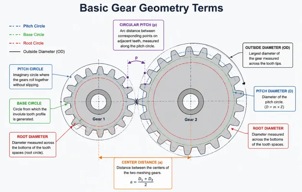
Gear geometry defines the size, shape, and meshing relationship of a gear. These fundamental dimensions determine whether two gears can mesh correctly, transmit motion efficiently, and meet the required performance specifications.
Pitch Circle
The pitch circle is an imaginary circle that represents where two mating gears theoretically roll together without slipping.
Pitch Diameter
The pitch diameter (d) is the diameter of the pitch circle and is one of the most important dimensions in gear design. It determines the gear’s size, center distance, and transmission ratio, and is commonly calculated from the module and number of teeth.
Base Circle
The base circle is the circle from which the involute tooth profile is generated.
Outside Diameter
The outside diameter (OD), also called the tip diameter, is the largest diameter of a gear measured across the tooth tips. It defines the gear’s maximum physical size and is commonly used for manufacturing and dimensional inspection.
Root Diameter
The root diameter is the diameter measured across the bottoms of the tooth spaces. It determines the root strength of the gear teeth.
Center Distance
The center distance (a) is the distance between the centers of two meshing gears. It is determined by the pitch diameters of both gears.
Circular Pitch
The circular pitch (p) is the arc distance between corresponding points on adjacent teeth, measured along the pitch circle.
Diametral Pitch
Diametral Pitch (DP) expresses the number of teeth per inch of pitch diameter and is the standard sizing system for gears designed in inch units. A higher DP indicates smaller, finer teeth, while a lower DP indicates larger teeth.
The module (m) is the metric unit used to define gear tooth size. It is calculated by dividing the pitch diameter by the number of teeth, with larger module values corresponding to larger and stronger gear teeth.
Module vs. Diametral Pitch
Both module and diametral pitch (DP) describe the size of gear teeth, but they use different unit systems. Module is the international standard for metric gears, while DP is primarily used for inch-based gear designs. They are inversely related by the conversion formula:
DP=25.4/m
Although the two systems describe the same gear characteristic, they are not directly interchangeable. Gears manufactured with different module or DP values cannot mesh correctly.
Gear Tooth Terminology
The geometry of an individual gear tooth determines how smoothly two gears mesh, how much load they can carry, and how efficiently they transmit motion.
Tooth Face
The tooth face refers to the portion of the tooth surface above the pitch circle.
Tooth Flank
The tooth flank is the portion of the tooth surface below the pitch circle. Together with the tooth face, it forms the complete involute tooth profile that guides smooth engagement and disengagement during operation.
Tooth Tip
The tooth tip, also called the top land, is the outermost surface of a gear tooth.
Tooth Root
The tooth root is the bottom portion of the tooth space where adjacent teeth meet. It experiences the highest bending stress during operation.
Tooth Thickness
Tooth thickness is the width of a gear tooth measured along the pitch circle.
Tooth Space
The tooth space is the gap between two adjacent gear teeth, which must be accurately matched to the tooth thickness of the mating gear.
Addendum
The addendum is the radial distance from the pitch circle to the tooth tip.
Dedendum
The dedendum is the radial distance from the pitch circle to the tooth root.
Whole Depth
The whole depth is the total radial height of a gear tooth, measured from the tooth tip to the tooth root. It equals the sum of the addendum and dedendum and defines the full tooth profile.
Working Depth
The working depth is the portion of the tooth height that actually engages with the mating gear. It is equal to the combined addendum of two mating gears and represents the effective depth of tooth contact during power transmission.
Tooth Profile Terminology
The shape of a gear tooth directly determines how smoothly power is transmitted between mating gears. Modern gears almost universally use the involute tooth profile because it satisfies the fundamental law of gearing.
Involute Profile
The involute profile is the standard tooth shape used for most gears today. It is generated by tracing the path of a taut string unwinding from the base circle, producing a tooth profile that maintains a constant angular velocity ratio throughout the meshing cycle.
Pressure Angle
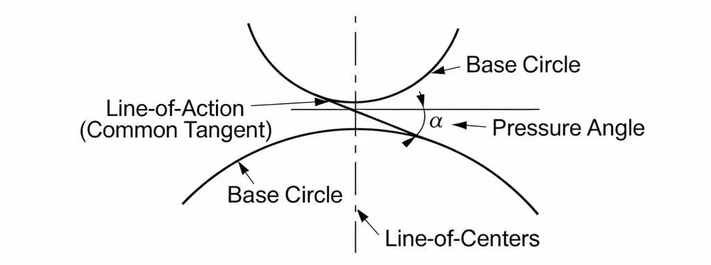
The pressure angle (α) is the angle between the line of action and the tangent to the pitch circle at the pitch point. Standard pressure angles are typically 20° and 25°, with 20° being the most widely used in the industry.
Base Pitch
The base pitch is the distance between corresponding points on adjacent involute teeth, measured along the base circle. For two involute gears to mesh correctly, they must have the same base pitch, ensuring continuous tooth engagement during rotation.
Line of Action
The line of action is the straight line along which force is transmitted between two mating gear teeth. It is tangent to both base circles and passes through the pitch point, forming the direction in which contact travels during meshing.
Contact Path
The contact path is the portion of the line of action over which two gear teeth remain in contact. It begins when a pair of teeth first engage (path of approach) and ends when they separate (path of recess). A longer contact path generally improves load sharing and contributes to smoother operation.
Contact Ratio
The contact ratio (ε) is the average number of tooth pairs simultaneously in contact during gear meshing. A contact ratio greater than 1.0 ensures continuous transmission, while values between 1.2 and 1.8 are commonly used in industrial gears to achieve smoother motion, lower vibration, and better load distribution.
Gear Design and Operating Parameters
Beyond basic geometry and tooth anatomy, gears are defined by several key design parameters that influence strength, transmission performance, noise, efficiency, and service life.
Number of Teeth
The number of teeth (Z) is the total count of teeth around a gear and is one of its most fundamental design parameters.
Gear Ratio
The gear ratio is the relationship between the number of teeth on two meshing gears, determining how rotational speed and torque are transmitted. A higher gear ratio reduces output speed while increasing transmitted torque, making it a key parameter in gearbox design.
Face Width
The face width (b) is the width of the gear tooth measured parallel to the gear axis.
Helix Angle
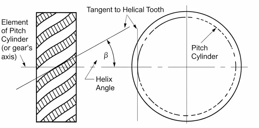
The helix angle (β) is the angle between the gear tooth and the gear axis in a helical gear. A larger helix angle increases tooth overlap and produces smoother, quieter operation, but it also generates greater axial thrust that must be supported by bearings.
Spiral Angle
The spiral angle defines the inclination of the curved teeth on a spiral bevel gear relative to the pitch cone.
Lead
The lead is the axial distance a helical gear tooth advances during one complete revolution around the gear. It describes the geometry of the helical tooth and is directly related to the helix angle.
Backlash
Backlash is the intentional clearance between mating gear teeth measured along the pitch circle.
Profile Shift
Profile shift is the intentional displacement of the gear cutting tool relative to the standard tooth profile during manufacturing.
Gear Manufacturing Terminology
While gear geometry defines how a gear should perform, manufacturing determines whether those design requirements can be achieved consistently. Gear manufacturing terminology will help you better understand how a gear is manufactured by various production process. Integration of different processes leads to gears with different specifications.
Gear Hobbing
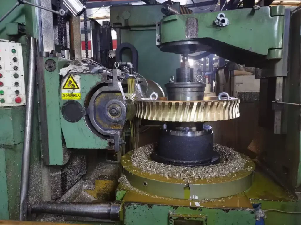
Gear hobbing is the most widely used gear cutting process, in which a rotating hob continuously generates gear teeth through synchronized motion with the workpiece. This is a process mainly for manufacturing spur gears, helical gears, splines, and sprockets in medium- to high-volume production.
Gear Shaping
Gear shaping uses a reciprocating cutter shaped like a gear to progressively generate the tooth profile. Compared with hobbing, it can machine internal gears, shoulder gears, and other geometries that are difficult or impossible to produce with a hob.
Gear Grinding
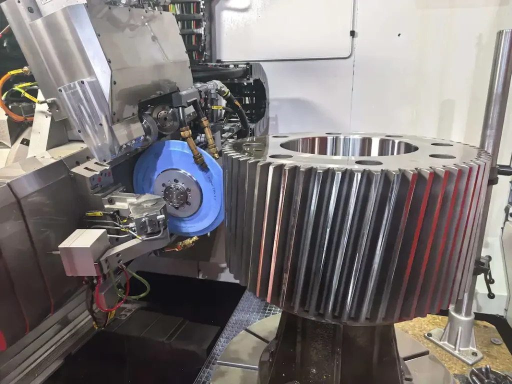
Gear grinding is a precision finishing process performed after heat treatment to achieve high dimensional accuracy and good tooth surface quality. It corrects distortion caused by hardening and is commonly used for high-speed, high-load, and precision transmission applications.
Gear Lapping
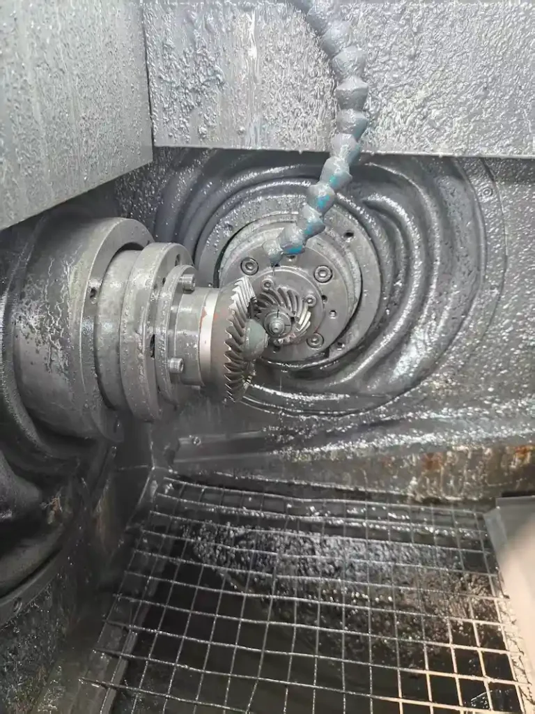
Gear lapping improves tooth surface finish by running mating gears together with a fine abrasive compound. This process enhances transmission smoothness, particularly for spiral bevel gears.
Gear Honing
Gear honing is a fine finishing process which removes microscopic surface irregularities from hardened gears using an abrasive honing tool. It improves surface texture, reduces transmission noise, and enhances fatigue performance but keeps the tooth geometry the same.
Gear Skiving
Gear skiving is a high-efficiency machining process in which the cutting tool and workpiece rotate at intersecting axes to generate gear teeth. It is particularly suitable for producing internal gears and complex gear geometries with shorter cycle times than conventional shaping.
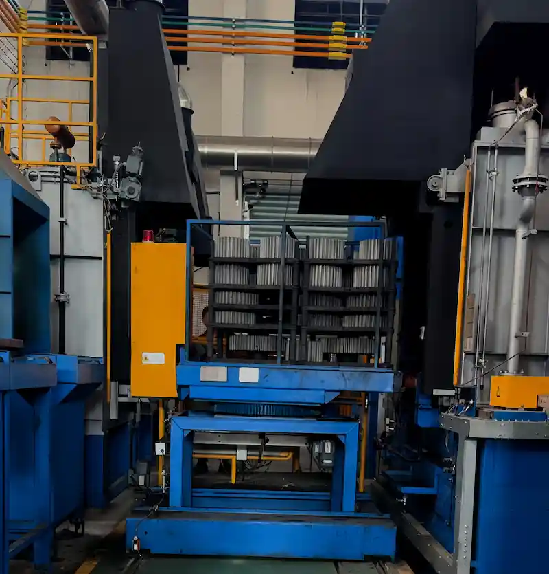
Heat treatment modifies the microstructure of gear materials to improve hardness, wear resistance, and fatigue strength. Common processes include carburizing, induction hardening, nitriding, and quenching and tempering, with the appropriate method selected according to material, load, and application requirements.
Shot Peening
Shot peening strengthens the tooth surface by bombarding it with small steel or ceramic shots, creating beneficial compressive residual stresses.
Superfinishing
Superfinishing is an ultra-precision surface treatment that removes microscopic asperities from gear teeth without altering their geometry. The resulting mirror-like surface reduces friction, minimizes micropitting, improves lubrication performance, and extends gear service life.
How BELON Delivers Custom Gear Manufacturing Solutions
At BELON, every gear manufacturing process is selected according to the customer’s application, material, accuracy grade, production volume, and performance requirements. Our engineering team develops the most suitable manufacturing route to achieve the required gear quality and service life.
Whether you need prototype development, small-batch production, or large-volume OEM manufacturing, BELON offers comprehensive customization for a wide range of gears—including spur gears, helical gears, bevel gears, worm gears, internal gears, and shafts. With in-house manufacturing capabilities and rigorous quality control, we deliver gear solutions tailored to your drawings, specifications, and application needs.
Gear Inspection Terminology
Even a perfectly designed gear cannot deliver reliable performance without accurate manufacturing and thorough inspection. Gear inspection verifies whether the finished gear meets dimensional, geometric, and accuracy requirements
Runout
Runout is the total radial deviation of a gear as it rotates about its axis.
Pitch Error
Pitch error is the deviation between the actual spacing of adjacent teeth and the theoretical pitch.
Profile Error
Profile error measures the difference between the actual tooth profile and the ideal involute curve.
Lead Error
Lead error is the deviation of the tooth trace from its intended direction across the face width.
Tooth Contact Pattern
The tooth contact pattern shows where mating gear teeth actually contact under operating conditions. A well-centered and evenly distributed contact pattern indicates proper gear geometry, alignment, and assembly, while abnormal patterns often reveal alignment or manufacturing problems.
Gear Accuracy Grade
A gear accuracy grade classifies the manufacturing precision of a gear according to standards such as ISO 1328, DIN, or AGMA.
CMM Inspection
A Coordinate Measuring Machine (CMM) uses a precision probe to measure multiple points on a gear tooth and reconstruct its three-dimensional geometry.
Double Flank Test
The double flank test evaluates the composite accuracy of a gear by meshing it with a precision master gear under light load while monitoring center-distance variation during rotation.
Common Gear Formulas Explained
Gear formulas provide the mathematical foundation for gear design, manufacturing, and inspection. Whether you’re calculating tooth size, determining the center distance between mating gears, or selecting the correct gear ratio, these equations are among the most frequently used in mechanical engineering. The following table summarizes the essential gear formulas used in both metric and imperial gear systems.
Common Gear Formula Reference
| Formula | Equation | Meaning | Typical Use |
| Module (m) | m = D / Z | Defines the size of each gear tooth in the metric system. | Gear design, tooth sizing |
| Diametral Pitch (DP) | DP = Z / D | Defines the number of teeth per inch of pitch diameter in the imperial system. | Inch-based gear design |
| Module ↔ DP Conversion | DP = 25.4 / m m = 25.4 / DP |
Converts between metric and imperial gear sizing systems. | International gear conversion |
| Pitch Diameter (D) | D = m × Z | Calculates the pitch diameter from the module and number of teeth. | Gear geometry, center distance |
| Outside Diameter (OD) | OD = m (Z + 2) | Calculates the outside diameter of a standard spur gear. | Manufacturing, inspection |
| Root Diameter (RD) | RD ≈ m (Z − 2.5) * | Estimates the root diameter of a standard full-depth gear. | Tooth strength evaluation |
| Gear Ratio (i) | i = Z₂ / Z₁ | Determines the speed reduction and torque multiplication between two gears. | Gearbox design |
| Center Distance (a) | a = (D₁ + D₂) / 2 | Calculates the distance between the centers of two meshing gears. | Assembly, gearbox layout |
| Circular Pitch (p) | p = πm | Calculates the arc distance between adjacent teeth on the pitch circle. | Tooth spacing |
| Base Pitch (pb) | pb = p × cos α | Calculates the tooth spacing along the base circle. | Involute gear meshing |
| Addendum (ha) | ha = m | Standard radial height above the pitch circle. | Tooth geometry |
| Dedendum (hf) | hf = 1.25m | Standard radial depth below the pitch circle. | Tooth clearance |
| Whole Depth (h) | h = 2.25m | Total tooth height from root to tip. | Gear manufacturing |
| Working Depth (hk) | hk = 2m | Effective depth of engagement between mating teeth. | Gear meshing |
Note: The root diameter formula shown is for a standard full-depth involute spur gear. Actual values may vary depending on the gear standard, profile shift, and tooth system.
Formula Symbols
| Symbol | Definition |
| m | Module |
| DP | Diametral Pitch |
| D | Pitch Diameter |
| OD | Outside Diameter |
| RD | Root Diameter |
| Z | Number of Teeth |
| Z₁ | Number of teeth on the driving gear |
| Z₂ | Number of teeth on the driven gear |
| a | Center Distance |
| p | Circular Pitch |
| pb | Base Pitch |
| α | Pressure Angle |
| ha | Addendum |
| hf | Dedendum |
| h | Whole Depth |
| hk | Working Depth |
Gear Terminology by Gear Type
While all gears share common terminology such as pitch diameter, module, addendum, and pressure angle, each gear type also has unique geometric features and design parameters. Understanding these specialized terms is undoubtedly helpful for you to better distinguish different gears.
Spur Gear
Spur gears are the simplest and most widely used gear type, featuring straight teeth parallel to the gear axis. Because they transmit power between parallel shafts, their geometry is defined primarily by radial parameters, making them the foundation for understanding gear terminology.
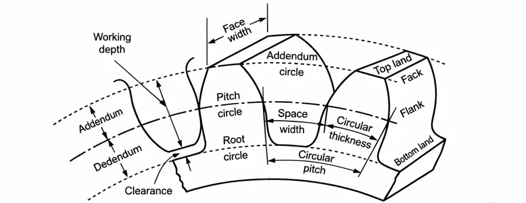
Key spur gear terms include:
- Module (m) – Defines tooth size.
- Pitch Diameter – Determines gear size and center distance.
- Outside Diameter – The maximum diameter measured across the tooth tips.
- Root Diameter – The diameter measured across the tooth roots.
- Pressure Angle – Defines the direction of transmitted force.
- Circular Pitch – The distance between adjacent teeth measured along the pitch circle.
Helical Gear
Helical gears have teeth cut at an angle to the gear axis. Helical gears introduce several other parameters related to the inclined tooth geometry.
Normal Module
The normal module (mn) is measured in the plane perpendicular to the tooth helix and is the standard module used for manufacturing helical gears.
Helix Angle
The helix angle (β) is the angle between the gear tooth and the gear axis. Larger helix angles generally improve load sharing and reduce noise but also increase axial thrust.
Lead
The lead is the axial distance a helical tooth advances in one complete revolution around the gear. It is determined by both the helix angle and the pitch diameter.
Axial Pitch
The axial pitch is the distance between corresponding points on adjacent teeth measured parallel to the gear axis. It is an important parameter for manufacturing and inspecting helical gears.
Bevel Gear
Bevel gears transmit power between intersecting shafts, typically at 90°, using teeth formed on a conical surface rather than a cylindrical one. As a result, several unique geometric terms are used to describe their design.
Cone Distance
The cone distance is the distance from the gear apex to the outer end of the pitch cone. It serves as the primary reference dimension for bevel gear geometry.
Pitch Cone
The pitch cone is the conical equivalent of the pitch circle in cylindrical gears. Two mating bevel gears roll together along their pitch cones to transmit motion.
Face Angle
The face angle defines the outer boundary of the gear tooth measured from the gear axis.
Root Angle
The root angle defines the lower boundary of the tooth root on the pitch cone and contributes to the overall tooth depth and strength.
Worm Gear
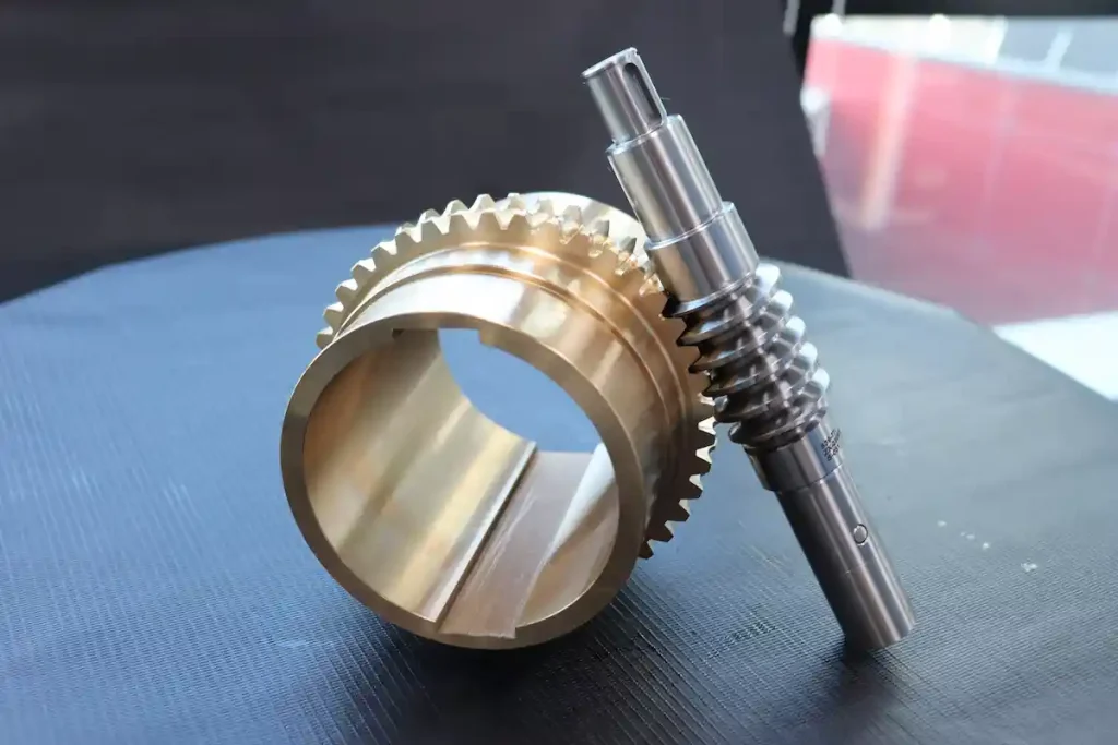
A worm gear set consists of a worm and a worm wheel, transmitting motion between non-parallel, non-intersecting shafts. Given that power is transmitted primarily through sliding contact, worm gears use several unique terminology related to the worm thread geometry.
Lead Angle
The lead angle (γ) is the angle between the worm thread and a plane perpendicular to the worm axis. It has a significant influence on transmission efficiency and self-locking characteristics.
Starts
Starts refer to the number of independent threads wrapped around the worm.
Lead
The lead is the axial distance the worm thread advances during one complete revolution. For a single-start worm, the lead equals the axial pitch, while for multi-start worms it equals the axial pitch multiplied by the number of starts.
Axial Pitch
The axial pitch is the distance between adjacent worm threads measured parallel to the worm axis. It determines the spacing of the threads and must match the mating worm wheel for proper engagement.
Gear Terminology Cheat Sheet
If you’re looking for a quick reference instead of reading the full guide, the table below summarizes the most important gear terminology used in design, manufacturing, inspection, and gear calculations. Bookmark this section as a practical reference for everyday engineering work.
Essential Gear Terminology Cheat Sheet
| Term | Definition | Formula (if applicable) | Why It Matters |
| Module | Metric tooth size | m = D / Z | Determines gear size |
| Diametral Pitch | Imperial tooth size | DP = Z / D | Defines inch gears |
| Pitch Circle | Theoretical rolling circle | — | Basis of gear geometry |
| Pitch Diameter | Diameter of the pitch circle | D = m × Z | Determines gear size |
| Base Circle | Generates the involute profile | — | Controls tooth geometry |
| Outside Diameter | Maximum gear diameter | OD = m(Z + 2) | Manufacturing & inspection |
| Root Diameter | Diameter at the tooth root | RD ≈ m(Z − 2.5) | Tooth strength |
| Circular Pitch | Tooth spacing on the pitch circle | p = πm | Proper meshing |
| Center Distance | Distance between gear centers | (D₁ + D₂)/2 | Gear assembly |
| Number of Teeth | Total tooth count | Z | Gear ratio calculation |
| Gear Ratio | Speed reduction ratio | Z₂ / Z₁ | Torque & speed transmission |
| Tooth Face | Surface above the pitch circle | — | Load transmission |
| Tooth Flank | Surface below the pitch circle | — | Guides tooth engagement |
| Tooth Tip | Outermost tooth surface | — | Defines outside diameter |
| Tooth Root | Bottom of the tooth space | — | Fatigue strength |
| Tooth Thickness | Tooth width on the pitch circle | — | Backlash control |
| Tooth Space | Gap between adjacent teeth | — | Tooth engagement |
| Addendum | Height above the pitch circle | ha = m | Working tooth height |
| Dedendum | Depth below the pitch circle | hf = 1.25m | Tip clearance |
| Whole Depth | Total tooth height | h = 2.25m | Manufacturing reference |
| Working Depth | Effective meshing depth | hk = 2m | Contact engagement |
| Involute Profile | Standard tooth curve | — | Constant velocity transmission |
| Pressure Angle | Direction of transmitted force | — | Load distribution |
| Base Pitch | Tooth spacing on the base circle | pb = p × cos α | Correct involute meshing |
| Line of Action | Force transmission line | — | Gear meshing principle |
| Contact Path | Distance teeth remain engaged | — | Smooth power transmission |
| Contact Ratio | Average tooth pairs in contact | ε | Noise & load sharing |
| Face Width | Width of the gear tooth | — | Load capacity |
| Helix Angle | Tooth inclination angle | β | Smoothness & axial thrust |
| Spiral Angle | Tooth inclination on bevel gears | — | Bevel gear geometry |
| Lead | Axial advance per revolution | — | Helical & worm gear geometry |
| Axial Pitch | Tooth spacing along the axis | — | Helical & worm gears |
| Lead Angle | Worm thread angle | γ | Efficiency & self-locking |
| Starts | Number of worm threads | — | Gear ratio |
| Profile Shift | Tooth profile modification | x | Strength & undercut prevention |
| Backlash | Clearance between mating teeth | — | Lubrication & thermal expansion |
| Gear Hobbing | Continuous gear cutting process | — | High-volume production |
| Gear Shaping | Reciprocating gear cutting | — | Internal gears |
| Gear Grinding | Precision finishing | — | High accuracy |
| Gear Lapping | Surface refinement with mating gears | — | Better contact pattern |
| Gear Honing | Fine finishing of hardened gears | — | Lower noise |
| Gear Skiving | High-efficiency gear machining | — | Internal & EV gears |
| Heat Treatment | Hardening process | — | Wear & fatigue resistance |
| Shot Peening | Surface strengthening | — | Fatigue life |
| Superfinishing | Ultra-smooth tooth surface | — | Reduced friction |
| Runout | Radial rotational deviation | — | Concentricity |
| Pitch Error | Tooth spacing deviation | — | Smooth meshing |
| Profile Error | Deviation from the involute profile | — | Load distribution |
| Lead Error | Tooth trace deviation | — | Contact alignment |
| Tooth Contact Pattern | Actual contact area | — | Assembly verification |
| Gear Accuracy Grade | Manufacturing precision level | — | Quality classification |
| CMM Inspection | 3D gear measurement | — | Precision inspection |
| Double Flank Test | Composite rolling test | — | Production quality control |
BELON Helps You Design and Manufacture Precision Gears
The terminology in this guide represents the foundation of gear engineering—but selecting the right combination of parameters is what makes a gear work reliably in a real application.
BELON can support you with the complete process:
Application Requirements → Design Review → Gear Calculation → Material Selection → DFM Optimization → Gear Manufacturing → Heat Treatment → Precision Finishing → Inspection → Final Delivery
Whether you have a complete gear drawing, an existing gear sample, or only the basic application requirements, BELON can work with your engineering team to develop a suitable manufacturing solution.
Need Custom Precision Gears?
Send BELON your drawings, specifications, samples, or application requirements. Our engineering team can review the requirements and recommend an appropriate gear design, material, manufacturing process, heat treatment, and inspection plan for your project.
[Request a Custom Gear Quote →]
FAQs
Q1: What is module in gear terminology?
The module (m) is the standard metric measurement used to define the size of a gear tooth. It is calculated by dividing the pitch diameter by the number of teeth:
m = D / Z
A larger module means larger, stronger teeth capable of transmitting higher loads, while a smaller module produces finer teeth suitable for compact, high-speed applications. For two gears to mesh correctly, they must have the same module and pressure angle.
Q2: What is the difference between module and pitch?
Although both terms describe gear tooth spacing, they refer to different concepts.
- Module is the metric measurement of tooth size, expressed in millimeters.
- Pitch generally refers to the spacing between adjacent teeth, such as circular pitch or base pitch, rather than the size of the teeth themselves.
In metric gear design, module is the primary sizing parameter, while pitch describes the distance between teeth.
Q3: What is pressure angle?
The pressure angle is the angle between the line of action and the tangent to the pitch circle at the pitch point. It determines the direction of force transmitted between mating gears and affects load capacity, radial force, and gear efficiency.
The most common standard pressure angle is 20°, although 25° is also used in heavy-duty applications requiring greater tooth strength.
Q4: What is backlash?
Backlash is the intentional clearance between the mating tooth surfaces of two gears. This clearance allows for lubrication, thermal expansion, and manufacturing tolerances while preventing tooth interference.
Q5: How do you calculate gear ratio?
The gear ratio is determined by comparing the number of teeth on the driven gear to the number of teeth on the driving gear:
Gear Ratio = Z₂ / Z₁
For example, if a 20-tooth pinion drives a 60-tooth gear, the gear ratio is 3:1. This means the output gear rotates at one-third the speed of the input gear while delivering approximately three times the torque, ignoring efficiency losses.
Q6: Why are involute gears used?
Most modern gears use the involute tooth profile because it satisfies the fundamental law of gearing, allowing two gears to maintain a constant angular velocity ratio throughout the meshing cycle.
Another major advantage is that involute gears can tolerate small variations in center distance while still transmitting motion smoothly, making them easier to manufacture, assemble, and maintain than alternative tooth profiles.