

Pinion gears are essential power transmission components that work with larger gears, racks, or ring gears to transfer motion, torque, and rotational speed efficiently. In this guide, you’ll learn what a pinion gear is, how it works, different types of pinion gears, common materials, manufacturing methods, applications, failure modes, and key selection factors.
What Is a Pinion Gear?

A pinion gear is the smaller gear in a meshing gear pair that transmits motion and power to a larger mating gear.
Pinion Gear Definition
The term pinion gear refers to the smaller member of a gear pair that meshes with a larger gear. In most gear systems, the pinion has fewer teeth and a smaller pitch diameter than the mating gear, and this correspondingly results in a higher rotational speed but lower output torque.
A pinion gear does not represent a unique gear type. Instead, “pinion” describes the function or position of a gear within a gear set. For example, a spur gear, helical gear, bevel gear, or hypoid gear can all be called a pinion if they are the smaller gear in the transmission pair.
The primary functions of a pinion gear include:
- Transmitting rotational motion between shafts
- Changing rotational speed through gear ratios
- Multiplying or reducing torque
- Reversing the direction of rotation when required
- Providing precise and repeatable motion control
Because of these functions, pinion gears are fundamental components in virtually every modern power transmission system.
Why Is It Called a Pinion Gear?
The word pinion originates from the Old French word pignon, meaning a small gear or toothed wheel. Over time, the term became widely adopted in mechanical engineering to describe the smaller gear that meshes with a larger companion gear.
Rather than indicating a specific gear geometry, the term identifies the gear’s relative size and role within a gear pair. Whether the gears are spur, helical, bevel, or hypoid, the smaller member is generally referred to as the pinion, while the larger member is simply called the gear, wheel, or ring gear, depending on the application.
For example:
- In a spur gear pair, the smaller spur gear is the pinion.
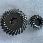
- In a spiral bevel gear set, the smaller bevel gear is the pinion.
- In a rack and pinion system, thecircular gear is the pinion, while the straight toothed component is the rack.
This naming convention is recognized by international gear design standards and is widely used across mechanical engineering industries up to now.
Pinion vs Gear: What’s the Difference?
The point what many people overlook is that, although the terms gear and pinion are often used interchangeably, they do not mean exactly the same thing.
A gear is a general term referring to any toothed mechanical component used to transmit power. A pinion gear, however, specifically refers to the smaller gear in a meshing pair. In most transmission systems, the pinion rotates faster and drives a larger gear to achieve speed reduction and torque multiplication.
The following table highlights the key differences.
| Feature | Pinion Gear | Gear |
| Relative Size | Usually smaller | Larger |
| Number of Teeth | Fewer teeth | More teeth |
| Pitch Diameter | Smaller | Larger |
| Rotational Speed | Higher RPM | Lower RPM |
| Torque | Lower input torque | Higher output torque |
| Primary Role | Often the driving gear* | Often the driven gear* |
| Typical Position | Input side | Output side |
| Common Applications | Steering systems, differentials, gearboxes | Gearboxes, reducers, transmissions |
How Does a Pinion Gear Work?
A pinion gear transmits mechanical power by meshing with a larger gear, ring gear, or rack. As the gear teeth engage continuously, rotational motion, speed, and torque are transferred from the driving shaft to the driven component.
Although pinion gears are used in many transmission systems, their operating principle is based on four fundamental concepts: gear meshing, torque transmission, speed reduction, and gear ratio.
Gear Meshing
Gear meshing is the continuous engagement between the teeth of a pinion gear and its mating gear. As one pair of teeth leaves contact, the next pair immediately engages to ensure uninterrupted power transmission.
Different from belt or chain drives, gears transmit motion through positive tooth engagement, which eliminates slipping and provides highly accurate rotational synchronization.
For smooth meshing, both gears must have matching design parameters, including the same module (or diametral pitch), pressure angle, and compatible tooth profile. Proper backlash and shaft alignment also help reduce vibration, noise, and wear.
Torque Transmission
When the driving shaft rotates, the pinion gear applies force to the mating gear through the contacting tooth surfaces. This tangential force transfers torque from the input shaft to the output shaft.
Because the load is distributed across multiple tooth contacts, gears can transmit high torque with excellent efficiency and reliability.
Speed Reduction
In most gear systems, the pinion has fewer teeth than the driven gear. As a result, the larger gear rotates more slowly while producing greater output torque.
For example, a 20-tooth pinion driving a 60-tooth gear creates a 3:1 reduction ratio. The pinion rotates three times while the larger gear completes one revolution.
This principle is commonly used in gear reducers, industrial transmissions, and automotive drivetrains where low speed and high torque are required.
Gear Ratio
The gear ratio determines how rotational speed and torque change between two meshing gears.
For a simple gear pair, the gear ratio is calculated as:
Gear Ratio = Number of Teeth on Driven Gear / Number of Teeth on Pinion
If both gears have the same module, the ratio can also be expressed using pitch diameters:
Gear Ratio = Pitch Diameter of Driven Gear/ Pitch Diameter of Pinion
A higher gear ratio reduces output speed while increasing output torque. Conversely, a lower gear ratio provides higher output speed with less torque multiplication.
Example
| Pinion Teeth | Gear Teeth | Gear Ratio | Output Speed | Output Torque |
| 20 | 40 | 2:1 | 50% | 2× |
| 20 | 60 | 3:1 | 33% | 3× |
| 25 | 100 | 4:1 | 25% | 4× |
Selecting the proper gear ratio is one of the most important considerations when designing an efficient transmission system, as it directly affects speed, torque, load capacity, and overall performance.
Types of Pinion Gears
Although all pinion gears perform the same basic function—transmitting motion and torque—their designs vary depending on the shaft arrangement and application requirements. Different tooth geometries are optimized for specific operating conditions, such as high-speed rotation, heavy loads, right-angle transmission, or linear motion.
The table below summarizes the most common types of pinion gears and their typical applications.
| Pinion Gear Type | Shaft Arrangement | Typical Applications |
| Spur Pinion Gear | Parallel Shafts | Industrial gearboxes, conveyors, machine tools |
| Helical Pinion Gear | Parallel Shafts | Automotive transmissions, compressors |
| Herringbone Pinion Gear | Parallel Shafts | Marine gearboxes, steel mills, mining equipment |
| Bevel Pinion Gear | Intersecting Shafts | Agricultural machinery, right-angle drives |
| Miter Pinion Gear | Intersecting Shafts | Packaging machinery, conveyors |
| Spiral Bevel Pinion Gear | Intersecting Shafts | Automotive differentials, marine gearboxes |
| Hypoid Pinion Gear | Offset Shafts | Passenger vehicles, trucks |
| Rack and Pinion Gear | Rotary to Linear Motion | Steering systems, CNC machines |
| Planetary Pinion Gear | Planetary Gear Systems | Automatic transmissions, robotics |
Pinion Gears for Parallel Shafts
Pinion gears used on parallel shafts are the most common in industrial power transmission, such as gearboxes, reducers, conveyors, compressors, and manufacturing equipment where both shafts remain parallel throughout operation.
Depending on the required speed, load capacity, and operating noise, engineers typically choose between spur, helical, and herringbone pinion gears.
Spur Pinion Gear
A spur pinion gear meshes with a larger spur gear through straight teeth that are parallel to the gear axis. It is the simplest and most economical type of pinion gear.
Because all teeth engage simultaneously, spur pinion gears offer high transmission efficiency and are easy to manufacture. However, they tend to generate more noise and vibration at higher speeds.

Advantages
- Simple structure
- Low manufacturing cost
- High transmission efficiency
- Easy maintenance
Limitations
- Higher operating noise
- Less suitable for high-speed applications
Typical Applications
- Industrial gearboxes
- Conveyors
- Packaging machinery
- Machine tools
Helical Pinion Gear
A helical pinion gear features teeth cut at a helix angle, allowing gradual tooth engagement. Compared with spur gears, this design produces smoother power transmission, lower vibration, and higher load capacity. Due to multiple teeth share the load simultaneously, helical pinion gears are commonly used in high-speed and heavy-duty transmission systems.

Advantages
- Smooth and quiet operation
- Higher load capacity
- Reduced vibration
- Suitable for high-speed transmission
Limitations
- Generates axial thrust
- Requires thrust bearings
- More complex manufacturing
Typical Applications
- Automotive transmissions
- Industrial reducers
- Compressors
- Pumps
Herringbone Pinion Gear
A herringbone pinion gear consists of two opposing helical tooth sets that form a V-shaped pattern. This configuration combines the smooth engagement of helical gears while eliminating axial thrust.
Its balanced tooth design enables exceptional load distribution and reliable operation under continuous heavy-duty conditions.

Advantages
- Eliminates axial thrust
- Excellent load capacity
- Smooth and quiet operation
- High transmission efficiency
Limitations
- Complex machining process
- Higher manufacturing cost
Typical Applications
- Marine gearboxes
- Steel mills
- Mining equipment
- Cement machinery
- Heavy industrial reducers
Pinion Gears for Intersecting Shafts
When two shafts intersect—typically at a 90° angle—bevel-type pinion gears are used to change the direction of power transmission while maintaining high efficiency.
Depending on the transmission requirements, engineers can choose straight bevel, miter, or spiral bevel pinion gears.
Bevel Pinion Gear
A bevel pinion gear meshes with a bevel gear to transmit motion between intersecting shafts. Straight bevel gears are commonly used in medium-speed applications where a compact right-angle drive is required.

Advantages
- Efficient right-angle transmission
- Compact structure
- Reliable torque transfer
Limitations
- Higher noise than spiral bevel gears
- Lower load capacity at high speeds
Typical Applications
- Agricultural machinery
- Construction equipment
- Industrial gearboxes
Miter Pinion Gear
A miter pinion gear is a special bevel pinion used in a 1:1 miter gear set. Both gears have the same number of teeth, allowing power to change direction without changing rotational speed or torque.
Miter pinion gears are ideal for compact right-angle drives where equal input and output speeds are required.

Advantages
- Constant 1:1 gear ratio
- Compact design
- Efficient direction change
Limitations
- No speed reduction
- No torque multiplication
Typical Applications
- Packaging machinery
- Food processing equipment
- Printing machines
- Conveyor systems
Spiral Bevel Pinion Gear
A spiral bevel pinion gear features curved teeth that engage gradually, producing smoother meshing than straight bevel gears. This design increases the contact ratio, improves load distribution, and significantly reduces vibration and noise.
Advantages
- Smooth and quiet operation
- High load capacity
- Excellent transmission efficiency
- Longer service life
Limitations
- Higher manufacturing precision required
- More complex machining and inspection
Typical Applications
- Automotive differentials
- Marine propulsion systems
- Mining machinery
- Wind turbines
- Industrial robots
Pinion Gears for Offset Shafts
When the shaft centerlines do not intersect or remain parallel, hypoid pinion gears provide an effective transmission solution.
Hypoid Pinion Gear
A hypoid pinion gear resembles a spiral bevel gear but operates with offset shafts. The offset increases tooth contact length, allowing the gear set to transmit higher torque while operating more quietly.
Because of their durability and smooth performance, hypoid pinion gears are widely used in automotive axle drives.

Advantages
- High torque capacity
- Quiet operation
- Excellent durability
- High contact ratio
Limitations
- Greater sliding action
- Requires specialized lubricants
Typical Applications
- Passenger vehicles
- Trucks
- Construction machinery
- Heavy-duty axle systems
Pinion Gears for Rotary-to-Linear Motion
Rack and Pinion Gear
Unlike conventional gear pairs, a rack and pinion system converts rotational motion into linear movement. The circular pinion rotates against a straight rack, causing the rack to move in a straight line.

How Do Rack and Pinion Gears Work?
As the pinion gear rotates, its teeth push against the rack teeth, converting rotary motion into controlled linear travel. Reversing the rotation direction causes the rack to move in the opposite direction.
Because there is no slippage between the teeth, rack and pinion systems provide precise positioning and high transmission efficiency.
Typical Applications
- Automotive steering systems
- CNC machine tools
- Linear actuators
- Industrial automation
Pinion Gears in Planetary Gear Systems
Planetary Pinion Gear
In a planetary gear set, the planet gears function as pinion gears because they simultaneously mesh with the central sun gear and the surrounding ring gear.
This arrangement distributes the transmitted load among multiple gear meshes, resulting in high torque density, compact size, and excellent efficiency.

Advantages
- High power density
- Compact design
- Excellent load sharing
- Multiple transmission ratios
Typical Applications
- Automatic transmissions
- Planetary gearboxes
- Industrial robots
- Servo systems
- Wind turbines
Ring and Pinion Gear: A Typical Automotive Application
A ring and pinion gear set consists of a small drive pinion and a large ring gear. Rather than representing a separate pinion gear type, it is a complete gear assembly commonly used in automotive differentials.
The drive pinion receives power from the driveshaft and meshes with the ring gear, redirecting power by 90 degrees while providing the final drive ratio. The selected gear ratio directly influences vehicle acceleration, towing performance, fuel economy, and maximum speed.
Typical Applications
- Passenger vehicles
- SUVs
- Pickup trucks
- Commercial vehicles
- Off-road and racing differentials
Common Materials for Pinion Gears
The material of a pinion gear directly affects its strength, wear resistance, fatigue life, corrosion resistance, and manufacturing cost. The following table compares the most commonly used materials and their typical applications.
| Material | Strength | Wear Resistance | Hardness (Typical) | Heat Treatment | Typical Applications |
| 20CrMnTi Alloy Steel | ★★★★★ | ★★★★★ | HRC 58–62 (carburized) | Carburizing + Quenching | Automotive transmissions, industrial gearboxes, agricultural machinery |
| AISI 8620 Alloy Steel | ★★★★★ | ★★★★★ | HRC 58–62 (carburized) | Carburizing + Quenching | Spiral bevel gears, pinion shafts, mining equipment, heavy-duty gearboxes |
| 18CrNiMo7-6 Alloy Steel | ★★★★★ | ★★★★★ | HRC 58–62 (carburized) | Carburizing + Quenching | Wind turbines, marine gearboxes, high-load industrial transmissions |
| Stainless Steel (304/316/420) | ★★★☆☆ | ★★★☆☆ | HRC 25–50 (depending on grade) | Optional hardening | Food processing, medical equipment, marine applications, corrosive environments |
| Brass | ★★☆☆☆ | ★★☆☆☆ | HB 80–150 | Generally not required | Instruments, clocks, light-duty drives, decorative mechanisms |
| Bronze | ★★★☆☆ | ★★★★☆ | HB 90–220 | Generally not required | Worm gear sets, marine equipment, low-noise transmissions |
| Engineering Plastic (POM, Nylon, PEEK) | ★★☆☆☆ | ★★★☆☆ | Varies by material | Not required | Printers, office equipment, consumer electronics, robotics, low-load automation |
How Are Pinion Gears Manufactured?
The manufacturing process of a pinion gear directly determines its precision, strength, durability, and transmission performance. High-quality pinion gears require strict control at every production stage, from raw material selection to final inspection.
A typical manufacturing process is illustrated below:

Forged Pinion Gear
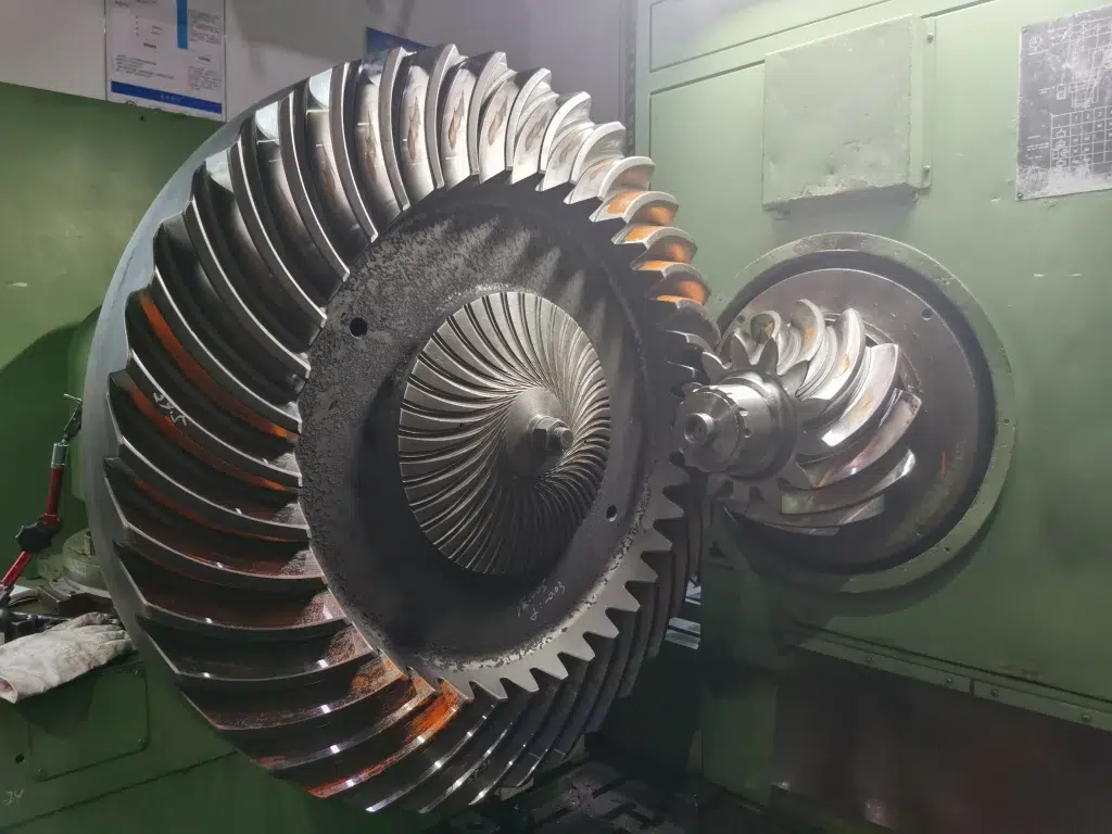
Forging is the preferred manufacturing method for medium- and heavy-duty pinion gears. During the forging process, heated steel billets are plastically deformed under high pressure to produce a near-net-shape gear blank.
Compared with cast or bar-stock components, forged pinion gears have a refined grain flow, fewer internal defects, and significantly higher strength and fatigue resistance.
Advantages
- Superior mechanical strength
- Improved impact and fatigue resistance
- Better grain flow structure
- Ideal for high-load applications
- Suitable for mass production
Typical Applications
- Automotive transmissions
- Spiral bevel pinion gears
- Mining machinery
- Construction equipment
- Wind turbine gearboxes
Machined Pinion Gear
Machined pinion gears are produced directly from steel bars or forged blanks using CNC turning, gear hobbing, shaping, milling, or machining centers.
Advantages
- High dimensional accuracy
- Flexible for custom designs
- Suitable for small batches
- Shorter development cycles
- Easy to modify during prototyping
Typical Applications
- Precision machinery
- Robotics
- Automation equipment
- Aerospace components
- Custom OEM gear projects
Heat Treatment
Heat treatment improves the hardness, wear resistance, fatigue strength, and service life of pinion gears. The appropriate process depends on the material, load requirements, and operating conditions.
| Heat Treatment | Surface Hardness | Core Toughness | Best For | Typical Materials |
| Carburizing + Quenching | ★★★★★ | ★★★★★ | Heavy-duty, high-load gears | 20CrMnTi, 8620, 18CrNiMo7-6 |
| Nitriding | ★★★★★ | ★★★★☆ | High wear resistance with minimal distortion | Alloy steels, nitriding steels |
| Induction Hardening | ★★★★☆ | ★★★★☆ | Localized hardening for medium-duty gears | Medium-carbon steels |
Carburizing
Carburizing diffuses carbon into the gear surface before quenching, producing a hard wear-resistant case while maintaining a tough core. It is the most widely used heat treatment for automotive and industrial pinion gears.
Nitriding
Nitriding introduces nitrogen into the surface to create an extremely hard wear layer with minimal dimensional distortion. It is ideal for precision gears that require excellent wear resistance without post-heat-treatment machining.
Induction Hardening
Induction hardening rapidly heats only the tooth surface using electromagnetic induction, followed by quenching. It provides localized hardening, short processing times, and excellent productivity for medium-duty applications.
Gear Grinding and Inspection
After heat treatment, high-precision pinion gears are typically finished by gear grinding or gear lapping to achieve the required tooth accuracy, surface finish, and contact pattern.
Grinding removes heat-treatment distortion and improves tooth profile accuracy, while lapping further optimizes tooth contact and reduces operating noise, particularly for spiral bevel gear sets.
Besides, before shipment, every pinion gear should undergo comprehensive quality inspection to ensure compliance with design specifications.
Typical inspection methods include:
| Inspection Item | Purpose | Equipment |
| Tooth Profile Inspection | Verify involute accuracy | Gear Measuring Center |
| Lead Inspection | Check helix accuracy | Gear Measuring Center |
| Pitch Measurement | Ensure tooth spacing accuracy | Gear Tester |
| Runout Inspection | Verify concentricity | Dial Indicator / CMM |
| Hardness Testing | Confirm heat treatment quality | Rockwell Hardness Tester |
| Surface Roughness | Measure tooth finish | Surface Roughness Tester |
| Tooth Contact Pattern | Verify gear meshing quality | Blue Contact Pattern Test |
| Dimensional Inspection | Check critical dimensions | CMM, Micrometer, Vernier Caliper |
Common Applications of Pinion Gears
Thanks to their ability to transmit power, adjust speed, multiply torque, and change the direction of motion, pinion gears are used in almost every mechanical transmission system. The specific design of a pinion gear varies depending on the industry’s performance, load, and precision requirements.
Industry Applications of Pinion Gears
| Industry | Typical Pinion Gear | Role of the Pinion Gear | Common Equipment |
| 🚗 Automotive | Spiral Bevel, Hypoid, Ring & Pinion | Transfers power from the driveshaft to the differential, changes the direction of rotation, and provides the final drive ratio for torque multiplication. | Passenger cars, trucks, SUVs, EV drivetrains |
| ⚙️ Industrial Gearboxes | Spur, Helical | Transmits power between shafts, reduces speed, and increases output torque for continuous industrial operation. | Gear reducers, conveyors, mixers, compressors |
| 🤖 Robotics | Planetary, Helical | Delivers precise motion control with low backlash, compact size, and high positioning accuracy. | Industrial robots, servo actuators, collaborative robots |
| 🚜 Agricultural Machinery | Bevel, Spur | Transfers engine power to implements and drivetrains while withstanding shock loads and harsh environments. | Tractors, harvesters, seeders, balers |
| ⛏️ Mining Equipment | Spiral Bevel, Helical | Handles extremely high torque and heavy impact loads in demanding operating conditions. | Crushers, conveyors, excavators, drilling equipment |
| 🚢 Marine | Spiral Bevel, Herringbone | Provides reliable right-angle power transmission with high load capacity and low vibration. | Marine gearboxes, propulsion systems, winches |
| 🌬️ Wind Energy | Planetary, Helical | Increases torque and transfers power from the rotor to the generator with high reliability. | Wind turbine gearboxes |
| 🏭 Industrial Automation | Rack & Pinion, Spur | Converts rotary motion into precise linear motion or synchronizes mechanical movements. | CNC machines, linear actuators, automated production lines |
Automotive
In automotive drivetrains, pinion gears are essential components of the differential and final drive system. A spiral bevel or hypoid pinion transfers power from the driveshaft to the ring gear, changing the direction of rotation while increasing output torque.
The selected ring-and-pinion ratio directly affects vehicle acceleration, climbing ability, fuel economy, and maximum speed.
Industrial Gearboxes
Industrial gearboxes rely on spur and helical pinion gears to transmit power efficiently between parallel shafts. These gears reduce rotational speed while increasing torque for heavy-duty industrial equipment.
High-quality pinion gears help improve transmission efficiency, reduce vibration, and extend gearbox service life.
Robotics
Modern robots require compact transmission systems with high precision and minimal backlash. Planetary and helical pinion gears provide accurate motion control while supporting rapid acceleration and repeated positioning.
These gears are commonly found in servo gearboxes, robotic joints, and precision automation equipment.
Agricultural Machinery
Agricultural equipment operates under dusty, muddy, and high-impact conditions. Pinion gears transfer engine power to working mechanisms while maintaining reliable performance under variable loads.
Durability and wear resistance are critical for ensuring long service life during seasonal operation.
Mining Equipment
Mining machinery places extreme demands on gear systems due to continuous heavy loads and severe operating environments. Spiral bevel and helical pinion gears are widely used because of their high load capacity and excellent durability.
Precision heat treatment and gear grinding are essential for maximizing fatigue strength in these applications.
Marine
Marine propulsion systems commonly use spiral bevel and herringbone pinion gears to transmit high torque smoothly and quietly. Their optimized tooth geometry helps minimize vibration while maintaining reliable operation under continuous load.
Corrosion-resistant materials and precision manufacturing are often required for long-term marine service.
Wind Energy
Wind turbine gearboxes use planetary and helical pinion gears to increase torque from the low-speed rotor before driving the high-speed generator.
Because maintenance is difficult and costly, wind power applications demand exceptional gear accuracy, fatigue resistance, and long operating life.
Industrial Automation
Rack and pinion systems are widely used in automation equipment to convert rotary motion into precise linear movement. They provide excellent positioning accuracy and repeatability for high-speed manufacturing processes.
Typical applications include CNC machine tools, automated assembly lines, gantry systems, and material handling equipment.

Common Pinion Gear Problems and Solutions
Even a high-quality pinion gear can experience wear or failure if it operates under excessive loads, poor lubrication, improper installation, or inadequate maintenance.
The table below summarizes the most common pinion gear problems, their causes, and recommended solutions.
| Problem | Common Cause | Recommended Solution |
| Excessive Wear | Poor lubrication, contaminated lubricant, abrasive particles | Replace lubricant regularly, use the correct gear oil, improve sealing |
| Tooth Breakage | Overload, impact loading, material defects | Use higher-strength materials, optimize gear design, avoid overload |
| Pitting | Contact fatigue, excessive contact stress, inadequate surface hardness | Apply carburizing or nitriding, improve lubrication, optimize tooth contact |
| Scuffing / Scoring | Insufficient lubrication, excessive temperature, high sliding friction | Use EP gear oil, improve cooling, reduce operating temperature |
| Excessive Noise | Incorrect backlash, gear wear, poor alignment, low machining accuracy | Adjust backlash, realign shafts, replace worn gears, improve gear accuracy |
| Misalignment | Installation error, bearing wear, shaft deflection | Realign shafts, replace worn bearings, verify installation tolerances |
| Corrosion | Moisture, chemical exposure, improper storage | Apply anti-corrosion coating, use stainless steel where required, improve storage conditions |
| Overheating | Overloading, poor lubrication, excessive operating speed | Reduce operating load, improve lubrication system, monitor operating temperature |
How to Choose the Right Pinion Gear
Selecting the right pinion gear is essential for those who want to obtain reliable performance, long service life, and efficient power transmission. In addition to choosing the correct gear type, engineers should comprehensively evaluate the operating conditions, material properties, manufacturing quality, and supplier capabilities.
Use the following checklist when selecting a pinion gear for your application.
| Selection Checklist | Why It Matters |
| Gear Type | Select the appropriate type (spur, helical, bevel, spiral bevel, hypoid, rack and pinion, etc.) based on shaft arrangement and transmission requirements. |
| Material | Choose materials such as 20CrMnTi, AISI 8620, 18CrNiMo7-6, stainless steel, bronze, or engineering plastics according to load and operating environment. |
| Module / Diametral Pitch | Ensure compatibility with the mating gear for proper tooth engagement and smooth power transmission. |
| Number of Teeth | Determines the gear ratio, affecting output speed, torque, and transmission efficiency. |
| Heat Treatment | Select carburizing, nitriding, or induction hardening to improve wear resistance and fatigue strength. |
| Accuracy Grade | Higher AGMA or ISO accuracy grades reduce noise, vibration, and transmission errors in precision applications. |
| Surface Finish | Ground or lapped tooth surfaces improve contact quality, reduce friction, and extend gear life. |
| Load Capacity | Evaluate both continuous and peak loads to ensure sufficient bending and contact fatigue strength. |
| Operating Speed | High-speed applications typically require precision grinding, dynamic balancing, and optimized lubrication. |
| Lubrication | Select the appropriate lubricant and lubrication method to minimize wear, friction, and heat generation. |
| Manufacturer Capability | Choose a manufacturer with in-house engineering, precision machining, heat treatment, grinding, inspection, and OEM customization capabilities. |
Quick Selection Tips
- For high-speed applications: Choose helical or spiral bevel pinion gears with precision-ground tooth surfaces.
- For heavy-duty equipment: Use carburized alloy steel such as 20CrMnTi, AISI 8620, or 18CrNiMo7-6.
- For corrosive environments: Consider stainless steel or bronze.
- For precision motion control: Select gears with a high ISO/AGMA accuracy grade and low backlash.
Why Choose Belon as Your Pinion Gear Manufacturer
Selecting the right pinion gear manufacturer is just as important as selecting the right gear design. A reliable manufacturing partner ensures consistent quality, engineering support, on-time delivery, and long-term transmission performance.
With decades of experience in precision gear manufacturing, Belon provides complete OEM and custom pinion gear solutions for customers across a wide range of industries, from industrial machinery and automotive systems to robotics, marine equipment, and renewable energy.
Whether you provide complete engineering drawings or only a sample component, our team can help transform your concept into a production-ready solution.
Why Customers Choose Belon
- Custom pinion gear solutions tailored to your application
- Complete in-house manufacturing from forging to final inspection
- Advanced CNC machining, gear grinding, and lapping capabilities
- In-house heat treatment for consistent quality control
- ISO-certified quality management system
- Comprehensive inspection using CMM, gear measuring systems, and metallographic analysis
- Prototype, small-batch, and high-volume production
- OEM & ODM manufacturing services
- Professional engineering support from design to delivery
- Reliable global supply with export experience across major international markets
Ready to Start Your Pinion Gear Project?
Whether you need a custom spur pinion, spiral bevel pinion, hypoid pinion, or a complete gear transmission solution, Belon provides the engineering expertise and manufacturing capabilities to support your project from concept to production.
Contact our engineering team today to discuss your application, request a quotation, or explore a customized pinion gear solution designed to meet your exact performance requirements.
FAQs
What is a pinion gear?
A pinion gear is the smaller gear in a meshing gear pair. It typically drives or is driven by a larger gear to transmit rotational motion and mechanical power.
Pinion gears are widely used to change speed, increase torque, alter the direction of rotation, or convert rotary motion into linear motion. Depending on the application, they can be designed as spur, helical, bevel, spiral bevel, hypoid, rack and pinion, or planetary pinion gears.
How does a pinion gear work?
A pinion gear works by meshing with another gear or rack. As the pinion rotates, its teeth engage with the mating component, transferring motion, torque, and speed through continuous tooth contact.
The output speed and torque are determined by the gear ratio. A smaller pinion driving a larger gear reduces speed while increasing torque, whereas a larger pinion driving a smaller gear increases speed but reduces torque.
What is the difference between a gear and a pinion?
A gear is a general term for any toothed mechanical component that transmits power. A pinion specifically refers to the smaller gear in a meshing pair.
In most gear systems, the pinion has fewer teeth, rotates at a higher speed, and often serves as the driving gear, while the larger gear rotates more slowly and delivers higher output torque. However, either gear can function as the driver depending on the transmission design.
What are the different types of pinion gears?
The most common types of pinion gears include:
- Spur pinion gears
- Helical pinion gears
- Herringbone pinion gears
- Bevel pinion gears
- Miter pinion gears
- Spiral bevel pinion gears
- Hypoid pinion gears
- Rack and pinion gears
- Planetary pinion gears
Each type is designed for different shaft arrangements, load capacities, operating speeds, and transmission requirements.
What commonly causes damage to the pinion gear?
The most common causes of pinion gear damage include inadequate lubrication, excessive loading, improper shaft alignment, poor installation, and long-term fatigue.
Other contributing factors include contaminated lubricants, incorrect backlash, insufficient heat treatment, and using materials that are unsuitable for the operating conditions. Regular inspection, proper lubrication, and correct installation are essential for maximizing service life.
What materials are used for pinion gears?
Pinion gears are commonly manufactured from 20CrMnTi, AISI 8620, and 18CrNiMo7-6 alloy steels because of their excellent strength, wear resistance, and fatigue performance after heat treatment.
Other materials include stainless steel for corrosion resistance, bronze for worm gear applications, brass for light-duty mechanisms, and engineering plastics such as POM, nylon, or PEEK for lightweight and low-noise applications.
Can a worn pinion gear be replaced?
Yes. A worn pinion gear can usually be replaced if the mating gear and associated components remain within acceptable wear limits. However, in many applications—especially automotive differentials and precision gearboxes—it is recommended to replace the entire gear set to ensure proper tooth contact, backlash, and transmission performance.
After replacement, the gear system should be correctly aligned, lubricated, and inspected before returning to service.
How do I choose the right pinion gear?
Choosing the right pinion depends on several factors, including the gear type, material, gear ratio, module, number of teeth, heat treatment, accuracy grade, operating load, speed, and lubrication requirements. Working with an experienced gear manufacturer can help optimize the design, material selection, and manufacturing process, ensuring the pinion gear meets your application’s performance, durability, and reliability requirements.