

Abstract: Gears and shafts are the two most fundamental components in mechanical power transmission. Gears transfer torque and change rotational speed between machine elements, while shafts support and transmit that rotational motion throughout the power transmission system. Understanding how gears and shafts work together — and how to select the appropriate combination for specific applications— is critical to ensuring reliable, long-term system performance.
What Are Gears and Shafts?
A gear is a rotating mechanical component with teeth cut into its surface. When two gears mesh, their teeth interlock and transfer rotational motion and torque from one gear to another. By varying the number of teeth between mating gears, engineers can increase or decrease rotational speed and orque as required.
A shaft is a cylindrical mechanical component that supports and transmits rotational motion. Gears are mounted onto shafts — either through interference fits, keyways, or spline connections — so that rotation is transferred efficiently from one element to the next. In most industrial transmission systems, shafts serve as the structural backbone of the transmission assembly, carrying the combined loads of torque, bending, and sometimes axial force that result from gear mesh forces.
Gears and shafts together form the core of virtually every mechanical power transmission systems, encompassing everything from simple two-gear arrangements to complex multi-stage industrial gearboxes.
How Gears and Shafts Work Together?
When a motor drives an input shaft, the gear mounted on it rotates and meshes with a mating gear on an output shaft. The gear ratio between the two gears determines whether the output shaft rotates faster or slower than the input, and whether torque is increased or reduced in proportion.
The shaft must be strong enough to carry all the forces generatedduring gear meshing without bending, twisting, or fatigue failure. Key design considerations include:
- Torsional stiffness— The shaft must resist twisting under the applied torque without excessive deflection.
- Bending stiffness—The gear meshing force generates a bending moment between the shaft’s bearing supports.
- Critical speed— At high rotational speeds, shaft diameter and span must be designed to avoid resonance.
- Connection method— Gears are fixed to shafts through keyways, splines, shrink fits, or bolted flanges, depending on the torque level and assembly requirements.
Proper design of both the gear and the shaft — and their connection — is crucial to achieving reliable torque transmission, acceptable noise levels, and long service life.
Types of Shafts Used with Gears
Different applications require different shaft configurations:
Gear Shaft (Pinion Shaft)
A gear shaft is a type of shaft component in which the gear is machined directly onto the shaft body, forming a single, integral unit. This design eliminates the need for a separate connection between the gear and the shaft, improving torsional rigidity and reducing the overall component count. Gear shafts are widely used in gearboxes, planetary gear systems, and high-speed transmission systems.
Spline Shaft
A spline shaft has a series of parallel keys (splines) cut longitudinally along its surface, which engage with matching internal splines in a gear hub. Spline connections allow the gear to slide axially along the shaft while transmitting full torque, making them ideal for applications requiring axial adjustment, such as automotive gearboxes and machine tool drives.
Output and Input Shafts
In a gearbox, the input shaft receives power from the motor, while the output shaft transmits power to the driven machine. These shafts are precisely designed to match the bearing arrangement, gear mounting, and sealing requirements of the gearbox housing.
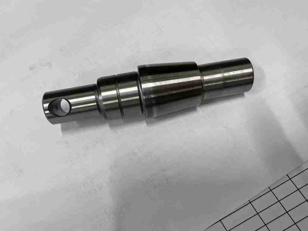
Intermediate Shaft (Counter Shaft)
In multi-stage gearboxes, intermediate shafts carry gears at both ends to transfer motion between the input and output stages. The number of intermediate shafts determines the number of reduction stages and the achievable overall gear ratio.
Materials for Gears and Shafts
Material selection for gears and shafts directly determines load capacity, wear resistance, fatigue life, and manufacturing costs. The most commonly used materials include:
- 20CrMnTi— A carburizing alloy steel widely used for gears in industrial gearboxes and automotive transmissions. After carburizing and quenching, it achieves high surface hardness with a tough core, resulting in excellent excellent wear resistance and impact strength.
- 42CrMo4— A through-hardening alloy steel suitable for heavy-duty shafts and large module gears. After quenching and tempering, it achieves an excellent balance of tensile strength, toughness, and fatigue resistance.
- 18CrNiMo7-6— A high-performance carburizing steel used in demanding applications such as wind turbine gearboxes and heavy industrial transmissions, featuring excellent surface hardness and core toughness.
Following rough machining, heat treatment processes—including carburizing, quenching, tempering, and induction hardening— are applied after rough machining to achieve the required hardness profile before final gear grinding and shaft finishing.
Industrial Applications of Gears and Shafts
Gears and shafts are core components in almost all industrial sectors:
- Industrial gearboxes— Multi-stage helical and bevel gear sets mounted on precision shafts deliver controlled speed reduction and torque multiplication for conveyors, mixers, and machine drives

- Mining and construction equipment— Large module gears and heavy-duty shafts transmit immense torques in crushers, excavators, and tunnel boring machines.

- Wind turbine gearboxes— High-precision helical gear sets and planetary gear sets on carburized shafts handle the variable loads generated by wind turbine operation.

- Robotics and automation— Compact gear and shaft assemblies enable precise motion control in robotic joints, servo drives, and automated production systems.

- Agricultural machinery— Bevel gears and shafts redirect and transmit power through the drivetrain of tractors, harvesters, and agricultural equipment.
Belon Custom Gears and Shafts Manufacturing
At Belon, we manufacture custom gears and shafts tailored to the specific requirements of each application. From gear type selection and shaft configuration to material specification, heat treatment, and dimensional tolerances, every component is engineered and produced to drawing.
Our manufacturing capabilities cover a wide range of gear types — including spur gears, helical gears, bevel gears, worm gears, and ring gears — paired with precision shafts including spline shafts, pinion shafts, output shafts, and custom stepped shafts. All components undergo rigorous dimensional inspection and quality control prior to delivery.
Whether you need a single prototype or high-volume production, Belon provides comprehensive gear and shaft solutions for industrial gearboxes, heavy machinery, automation, and custom transmission applications. Contact our engineering team today to get your tailor made gear and shaft solutions!
FAQs
Q1: What is the difference between a gear shaft and a shaft with a mounted gear?
A gear shaft has the gear teeth cut directly into the shaft body as a single component, offering higher torsional rigidity and a more compact design. A shaft with a mounted gear uses a separate gear fixed to the shaft via a keyway, spline, or interference fit, allowing easier replacement of the gear independently of the shaft.
Q2: How is a gear connected to a shaft?
The most common connection methods are keyway and key (suitable for moderate torque), spline connection (for high torque and axial sliding requirements), interference fit (for permanent, high-torque connections), and bolted flanges (for large gears requiring disassembly).
Q3: What causes gear and shaft failure in industrial applications?
Common failure modes include surface fatigue (pitting) from excessive contact stress, gear tooth bending fatigue from overload, shaft fracture from bending or torsional fatigue, and wear from inadequate lubrication or misalignment. Proper gear and shaft design, material selection, heat treatment, and lubrication are all critical to preventing premature failure.
Q4: Can Belon manufacture custom gear and shaft assemblies?
Yes. Belon manufactures custom gear and shaft components to customer drawings and specifications, covering a wide range of gear types, shaft configurations, materials, and accuracy grades.