
The primary advantage of custom ground bevel gear lies in its post-heat-treatment finishing process. After the gear is cut (hobbed or milled) from a steel blank, it undergoes heat treatment such as carburizing or induction hardening. This process creates a hard, wear-resistant case (58–62 HRC) over a tough, ductile core. However, heat treatment invariably causes thermal distortion—tooth profiles shift, pitch circles run out, and bores may warp. Grinding corrects these distortions using a high-speed abrasive wheel to remove just 0.05–0.15 mm of material from the tooth flanks, restoring geometry to AGMA Q12–15 (DIN 1–4) quality grades. In practical terms, this reduces transmission error to near zero, lowers audible whine, and increases gear life by 300–500% compared to non-ground gears.

Custom ground bevel gear manufacturing
Customized Ground Bevel Gear: The Gold Standard for High-Performance Drivelines
In modern mechanical power transmission, few components face as much simultaneous stress as the bevel gear. Tasked with changing torque direction by 90 degrees while handling high speeds and heavy loads, this component demands extreme precision. For applications ranging from aerospace actuators to electric vehicle (EV) reducers and industrial robot joints, a standard off-the-shelf part rarely suffices. This is where the custom-made ground bevel gear becomes indispensable, offering unparalleled accuracy, surface finish, and load capacity.
Designing a customized ground bevel gear starts with application-specific parameters: torque (Nm), input speed (rpm), center distance, gear ratio, and spatial constraints. Unlike lapped gears, which are matched in pairs, ground gears are manufactured to such tight tolerances that individual gears are fully interchangeable. This is critical for field service—if one gear in a pair is damaged, only that component needs replacement, not the matched set. The grinding process also allows for micro-geometry modifications such as tip relief, root relief, and crowning (barreling along the tooth length). These modifications compensate for housing deflection under load, ensuring that the contact patch remains centered on the tooth flank rather than shifting to the edges, where edge loading causes premature pitting or fracture.
In practice, a customized ground bevel gear finds homes in helicopter tail rotors (where failure is not an option), Formula 1 transmissions (where every gram and millimeter matters), and precision machine tool spindles (requiring backlash below 0.02 mm). While the manufacturing cost is significantly higher than that of cut-only or lapped gears—often 4–6 times more expensive—the lifecycle value justifies the investment in critical applications. When you demand zero compromise on noise, efficiency, and reliability, the solution is clear: specify a customized ground bevel gear from a qualified manufacturer equipped with CNC grinders and a temperature-controlled metrology lab.

6-Step Production Process

Forging
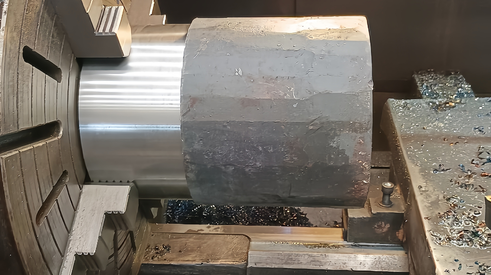
Turning
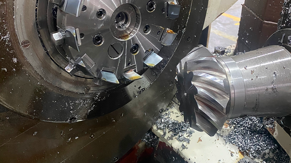
Gear Milling
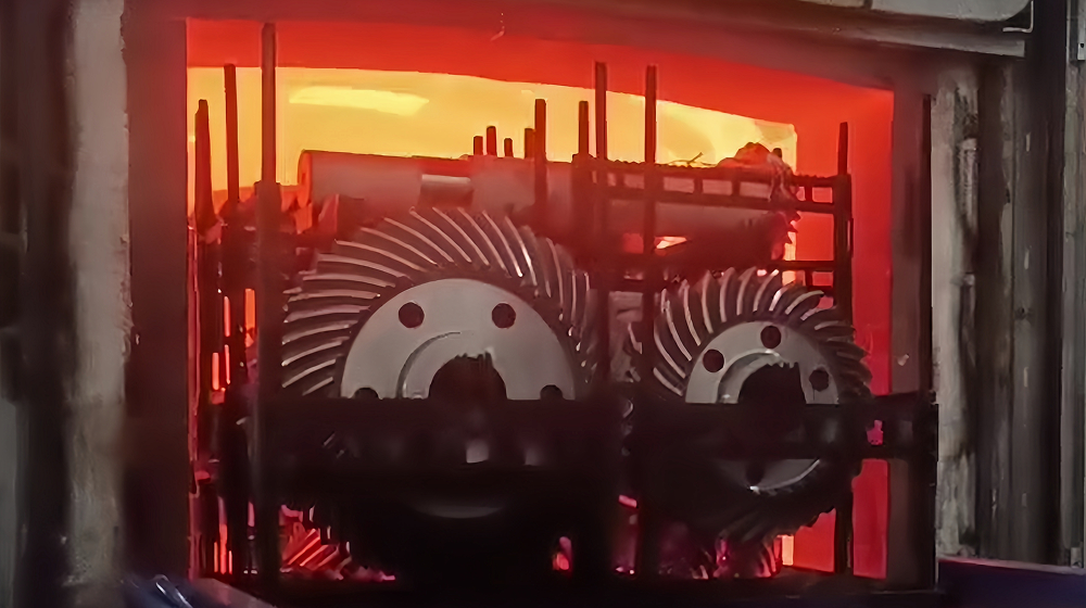
Heat Treatment
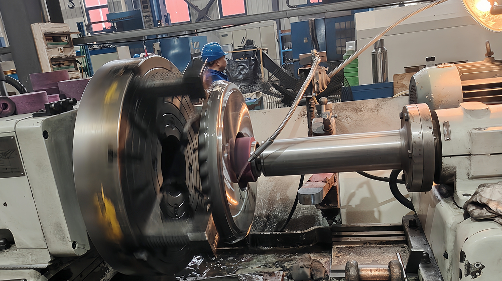
ID & OD Grinding
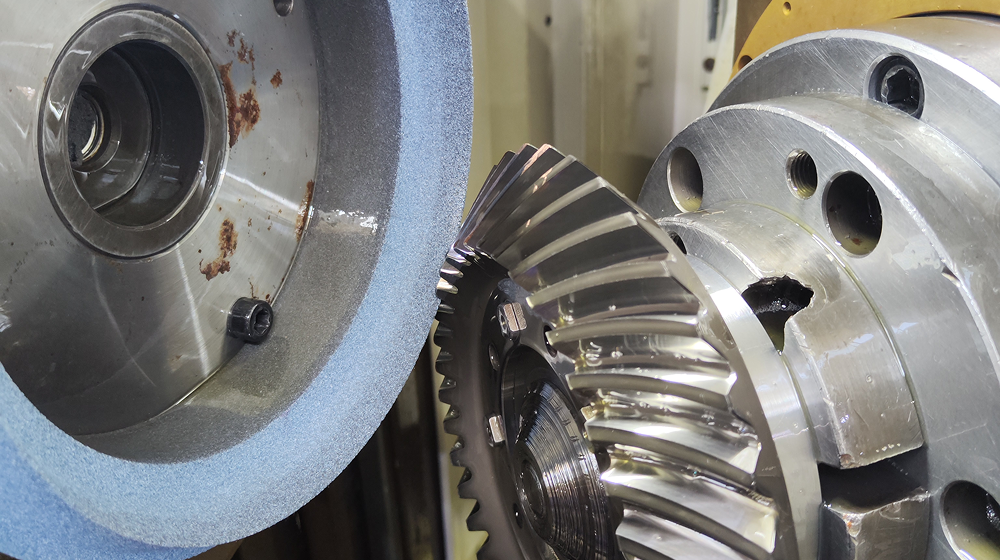
Tooth Grinding
Strict Quality Inspection
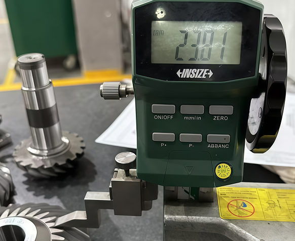
Dimension Inspection
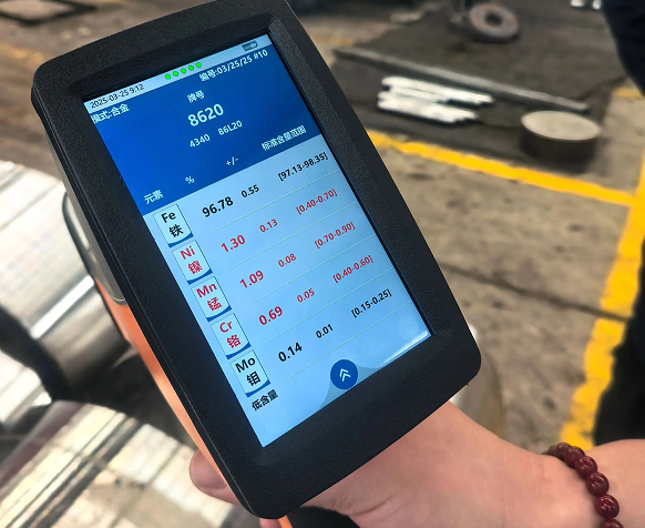
Material Testing
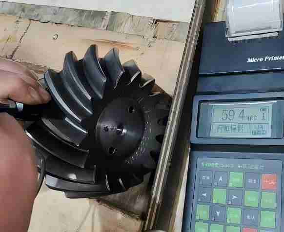
Hardness Inspection
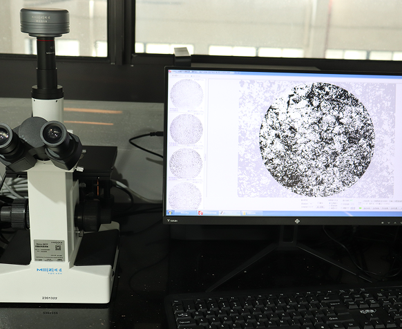
Heat Treatment Testing
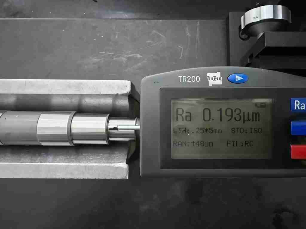
Roughness Testing
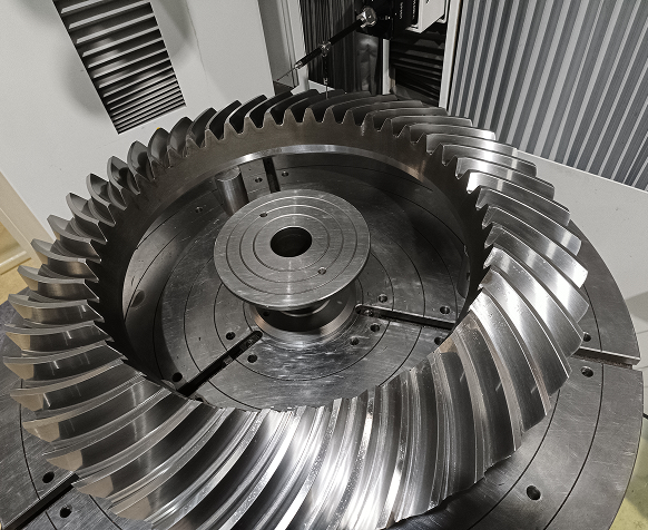
Accuracy Inspection
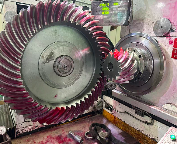
Meshing Testing
Dimension Inspection
Material Testing
Hardness Inspection
Heat Treatment Testing
Roughness Testing
Accuracy Inspection
Meshing Testing
Professional Packaging Safe Arrival

Inner Package
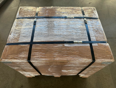
Out Package

Carton
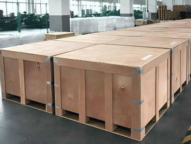
Wooden Package
You May Be Interested In

Precision Bevel Gears For Industrial Robot
- Material: 18CrNiMo7-6
- Heat treatment: Carburizing + Quenching + Tempering
- Accuracy: DIN 5

Spiral Bevel Gears For Automobiles
- Material: 20CrNiMoH
- Heat treatment: HRC 58-62
- Accuracy: GB/T 11365-2019

Ground Gear Bevel Gear
- Material: 18CrNiMo7-6
- Heat treatment: Carburizing + quenching + tempering
- Accuracy: DIN 4
