

Abstract: Learn how straight bevel gear planing improves gear meshing accuracy, transmission efficiency, and durability. Explore straight bevel gear manufacturing, machining processes, cutting methods, applications, and industrial gearbox solutions.
What Are Straight Bevel Gears?
Straight Bevel Gears Definition and Working Principle
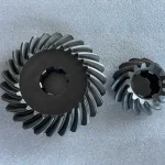
Straight bevel gears are cone-shaped mechanical components featuring straight, tapered teeth designed to transmit rotational motion and torque between intersecting shafts, most commonly at a 90 degree angle. They serve as the foundational solution for reliable right-angle power transmission in compact industrial drivetrains.
Also known in industrial manufacturing as straight cut bevel gears or straight tooth bevel gears, these components are critical for heavy-duty machinery. When parallel shafting isn’t an option, these intersecting shaft gears step in to redirect mechanical force smoothly without sacrificing torque.
The underlying working principle relies on the rolling contact of two matching conical surfaces. As the driving shaft rotates, the straight bevel gear profiles engage along lines that point directly toward a central intersection apex. This synchronized meshing ensures highly efficient 90 degree gear transmission, making them a staple in high-load gearboxes, heavy equipment, and standard industrial drive systems.
Key Components of a Straight Bevel Gear Set
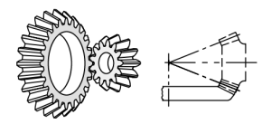 To understand how these gears maintain precision under load, we have to look closely at their unique conical gear geometry. A standard straight bevel gear set (see in the figure) consists of two primary intersecting parts:
- Bevel Pinion: The smaller driving gear in the set, typically connected to the power source (such as an electric motor or input shaft).
- Mating Gear: The larger driven gear that meshes with the pinion to alter output speed and multiply torque.
Unlike standard spur gears that mesh on flat cylinders, bevel gears operate along an imaginary pitch cone. The teeth are engineered as tapered gear teeth, meaning their profile and thickness gradually shrink as they approach the cone’s peak apex.
Because of this tapering, monitoring the tooth contact pattern during assembly is absolutely vital. Quality control technicians inspect this pattern to ensure that when the bevel pinion and mating gear lock together, the mechanical load is distributed evenly across the tooth flank rather than concentrating on the fragile edges, preventing premature pitting or tooth breakage.
Why Straight Bevel Gears Are Used in Mechanical Power Transmission
In modern industrial engineering, the straight bevel gear remains a dominant choice for a mechanical power transmission gear due to its specific geometric strengths and operational dependability.
First and foremost, their capacity for high-capacity torque transmission is exceptional. The rigid, cone-based structure allows them to absorb substantial shock loads for heavy-duty machinery like mining conveyors, steel rolling mills, and agricultural equipment.
Furthermore, they deliver excellent gearbox efficiency. Because the teeth engage all at once along the full face width, there is minimal axial thrust generated compared to spiral alternatives. This clean rotational motion transfer means less friction, lower operating temperatures, and maximum power delivery through the powertrain. Ultimately, their straightforward design translates directly into long-term transmission reliability and simplified field maintenance.
What Is Straight Bevel Gear Planing?
How Gear Planing Works in Straight Bevel Gear Manufacturing

In high-precision manufacturing, straight bevel gear planing stands out as the traditional, time-tested standard for generating flawless tooth profiles. Unlike high-speed mass production methods that compromise on geometric perfection, this specialized metal cutting process relies on a reciprocating motion to carve out each tooth path precisely.
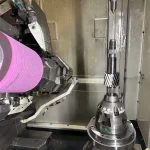
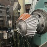
The process is executed on a heavy-duty gear planing machine, a highly specialized piece of equipment designed specifically for bevel gear tooth cutting. The machine utilizes two reciprocating cutting tools that move back and forth along the lines of the pitch cone, pointing directly toward the gear’s theoretical apex.
As the gear blank undergoes a synchronized generating roll, these tools perform continuous chip removal machining. By slicing away micro-layers of metal sequentially, gear planing ensures that the resulting tapered tooth profiles match the ideal mathematical envelope. It is the steady, controlled nature of this stroke-by-stroke cutting that makes it indispensable for large-scale, heavy-duty industrial gears.
Other Cutting Methods: Milling, Shaping, and Hobbing
While planing is highly respected for heavy-duty applications, engineers utilize a variety of other bevel gear cutting methods depending on production volume, gear size, and required precision. The chosen tooth generation method dictates both the manufacturing speed and the final quality of the gear set.
- Straight Bevel Gear Shaping: This method utilizes a circular cutter that rolls with the workpiece. While faster than planing for small to medium-sized gears, straight bevel gear shaping faces mechanical limitations when scaling up to massive, high-torque industrial sizes.
- Straight Bevel Gear Hobbing: Primarily used for continuous high-volume production, straight bevel gear hobbing employs a specialized conical hob tool. It yields excellent throughput but requires complex, expensive tooling configurations.
- Milling: A form-cutting process where a rotating cutter matches the tooth space gap. It is highly flexible for rapid prototyping or emergency repair jobs, though it generally falls short in high-precision gear synchronization.
To help you choose the right process for your project, here is a direct comparison of the industry’s primary cutting methods:
| Machining Method | Typical Gear Accuracy Grade (ISO/AGMA) | Typical Surface Roughness Ra (μm) | Production Volume | Typical Application | Tooling & Machine Cost |
| Gear Planing | ISO 6–8 / AGMA 10–12 | 1.6–3.2 μm | Medium to Large Batch | Heavy-duty straight bevel gears, industrial gearboxes, crane gears | Moderate |
| Gear Shaping | ISO 7–9 / AGMA 8–10 | 3.2–6.3 μm | Small to Medium Batch | Custom bevel gears, internal gears, repair manufacturing | Moderate to High |
| Gear Hobbing | ISO 6–8 / AGMA 9–11 | 1.6–3.2 μm | High-Volume Production | Automotive gears, standard transmission gears | High |
| Gear Milling | ISO 9–11 / AGMA 6–8 | 3.2–12.5 μm | Prototype or Low Volume | Gear repair, prototype machining, simple gear cutting | Low |
| Gear Grinding | ISO 3–5 / AGMA 12–15 | 0.4–1.6 μm | Precision Production | Aerospace gears, high precision industrial gears | Very High |
Advantages of Gear Planing for Precision Bevel Gear Machining
For critical industrial projects, opting for precision bevel gear machining via the planing method provides unmatched mechanical advantages. The fundamental design of a planer allows for an exceptional degree of rigid control over the cutting tool’s path, translating directly into superior field performance.
- Tight Machining Tolerance: The rigid mechanical guides of reciprocating blades virtually eliminate deviations across the tapered tooth flank, drastically reducing localized stress under heavy loads.
- Minimal Surface Roughness: The continuous, controlled stroking action yields a highly polished finish, resulting in less friction, lower heat generation, and quieter gearbox operation.
- Flawless Backlash Control: Meticulous tool feed adjustments ensure a perfectly uniform gap between meshing teeth, maximizing gear meshing accuracy and extending operational lifespan.
Straight Bevel Gear Manufacturing Process
To manufacture high-precision, industrial-grade gears, factories must follow a rigorous, step-by-step production flow. This comprehensive process transforms raw metal into a synchronized, high-torque mechanical component built to endure harsh working environments.
Raw Material Selection for Forged Straight Bevel Gears
The lifetime of any gear set begins with metallurgy. For high-stress applications, a forged straight bevel gear is vastly superior to cast options because the forging process aligns the metal’s grain structure with the shape of the teeth.
Manufacturers typically select high-grade alloy steel bevel gear blanks—such as 20CrMnTi, 8620, or 18CrNiMo7-6. These materials provide the core toughness required to create durable bevel gears that resist shock loads. Selecting the correct chemistry ensures that the final heavy duty bevel gears can withstand immense operational pressures without experiencing sudden fatigue failure or structural cracking.
Gear Cutting and CNC Machining Technology
Once the blank is forged and normalized, it enters the primary shaping stage. Modern facilities combine classic gear generation geometry with advanced CNC machining technology to turn the blank into a highly precise component.
During bevel gear machining, the blank is mounted onto a high-precision indexing mechanism. This mechanism rotates the blank with micro-degree accuracy between each cutting stroke or rotation in order to ensure perfectly uniform spacing. The cutting tools then carve out the exact gear tooth profile. This ensures the appropriate face width, addendum, and dedendum modifications are machined cleanly into the conical face.
Heat Treatment and Gear Tooth Hardening
Raw machined steel is too soft to survive thousands of operational hours under load. Therefore, gears undergo a strict thermal process to create heat treated bevel gears with a hard outer shell and a ductile, shock-absorbing core.
- Carburizing: The gears are placed in a carbon-rich furnace atmosphere, forcing carbon to diffuse into the surface layers of the teeth.
- Quenching & Tempering: Rapid cooling freezes the crystalline structure into an ultra-hard martensite matrix, followed by controlled reheating to eliminate internal brittleness.
The result is a batch of highly resilient carburized bevel gears. These hardened bevel gear teeth can resist localized surface pitting and abrasive wear while the softer core flexes safely under sudden impact spikes.
Gear Grinding and Tooth Finishing Process
Thermal hardening inevitably introduces minor dimensional distortions in the metal. To correct these micro-warps, the gear set undergoes a meticulous gear tooth finishing phase.
Through straight bevel gear grinding, specialized CNC grinding wheels shave away micron-level imperfections from the hardened tooth flanks. This step drastically reduces the final surface roughness for creating a mirror-like finish. Refining these dimensions elevates the component’s overall gear accuracy grade (such as achieving AGMA 11 or DIN 6 standards), to make sure exceptionally quiet operation and minimal frictional drag inside the housing.
Gear Inspection Process and Quality Control
The final step is verification. No gear leaves the shop floor without passing a rigorous gear inspection process to ensure full compliance with the client’s mechanical drawings.
- CMM Dimensional Auditing: Coordinate Measuring Machines map the absolute geometric coordinates of the gear teeth to ensure every machining tolerance is strictly met.
- Roll Testing: The finished component is meshed with a master gear or its actual mating partner to analyze the tooth contact pattern.
Checking the pattern ensures that the actual load distribution occurs perfectly across the center of the tooth flank. Verifying this contact profile guarantees smooth power transfer, eliminates localized stress points, and ensures the entire drivetrain performs reliably in the field.
Straight Bevel Gear vs Spiral Bevel Gear

When designing a right-angle drive system, engineers inevitably face a critical choice: should they specify a straight bevel gear or a spiral bevel gear? While both types operate on intersecting shafts, their tooth geometry creates vastly different operational characteristics, performance limits, and manufacturing costs.
Structural Differences Between Straight and Spiral Bevel Gears
The primary distinction between these two gear families lies in the physical curve and orientation of the teeth across the pitch cone face.
- Straight Bevel Gears: Feature straight, uncurved teeth that run directly parallel to the cone generator line, pointing straight toward the theoretical apex. The teeth engage along their entire face width simultaneously.
- Spiral Bevel Gears: Feature teeth trace along a helical, curved path across the pitch cone. This oblique tooth angle creates a gradual, progressive engagement from one end of the tooth to the other.
Noise, Load Capacity, and Transmission Efficiency Comparison
Because of these structural variations, straight and spiral configurations perform differently under high-speed or heavy-torque operational demands.
- Noise and Vibration: In straight bevel setups, full-line tooth contact occurs instantaneously. This abrupt engagement causes minor, periodic impacts, creating audible whine at higher operating speeds. Conversely, the gradual meshing of spiral teeth yields highly effective vibration reduction and smoother operation, making them the industry choice for low noise bevel gears in high-RPM applications.
- Load Capacity: Because spiral teeth are curved, they have a larger total contact ratio, meaning multiple teeth share the load at any given moment. This allows spiral designs to function perfectly as high load transmission gears. Straight bevel gears have a smaller contact ratio, making them more vulnerable to localized stress concentration during peak shock events.
- Power Transmission Efficiency: Both designs offer exceptional mechanical performance. Straight bevel gears yield an impressive power transmission efficiency of roughly 96% to 98% per set because they do not generate substantial axial thrust. Spiral bevel gears match this efficiency but generate complex, omnidirectional thrust loads that require heavier, specialized support bearings within the housing.
| Performance Metric | Straight Bevel Gears | Spiral Bevel Gears |
| Tooth Geometry | Straight, tapered lines | Curved, helical paths |
| Meshing Type | Instantaneous full-line contact | Gradual, progressive engagement |
| Noise & Vibration | Moderate to High (Best for low RPM) | Extremely Low (Ideal for high RPM) |
| Axial Thrust Load | Minimal / Low | High (Requires robust thrust bearings) |
| Manufacturing Cost | Economical and straightforward | High (Requires advanced multi-axis CNC) |
Which Gear Type Is Better for Heavy-Duty Applications?
The answer depends entirely on your specific operating speeds, required torque output, and budgetary targets.
For high-speed, high-stress environments where downtime is unacceptable—such as main drive automotive differentials or high-RPM aerospace gearboxes—spiral bevel designs are generally superior due to their continuous contact strength.
However, for low-speed, high-impact industrial applications, heavy duty bevel gears with a straight-cut tooth profile remain highly advantageous. In heavy equipment like mining slag crushers, agricultural scrapers, or low-speed material handling conveyors, operating speeds are slow enough that tooth noise is irrelevant.
In these scenarios, straight bevel gears provide unmatched transmission durability. Their simple design eliminates the complex axial thrust forces that wear out bearing housings prematurely, and they are significantly more cost-effective to manufacture in large custom sizes. For slow, brutal, high-torque right-angle power transfer, the straight bevel gear is frequently the most dependable and economical solution.
Industrial Applications of Straight Bevel Gears
Straight bevel gears serve as the critical mechanical backbone across numerous heavy industries. By providing dependable right angle power transmission, these robust components allow engineers to design compact, high-torque industrial drive systems that keep global supply chains moving.
Crane Bevel Gears for Heavy Load Transmission
In overhead cranes, gantry systems, and heavy-duty hoists, safety and load-bearing capacity are non-negotiable. Crane bevel gears for heavy load transmission are integrated into the main travel drives and hoisting mechanisms to redirect motor torque smoothly. Because cranes frequently experience sudden start-stop movements and heavy shock loads when lifting tons of material, the rigid, tapered structure of straight bevel gears ensures reliable operation without the risk of tooth shearing, maintaining maximum safety during overhead operations.
Industrial Gearbox Bevel Gears
Standard and custom-built industrial gearbox bevel gears are foundational to modern factory automation and manufacturing plants. Whenever an electric motor’s horizontal output must turn a vertical shaft—or vice versa—straight bevel gears act as highly efficient power transmission gears. They deliver precise rotational speed reduction and torque multiplication within the gearbox housing, suffering minimal frictional energy loss and generating negligible axial thrust, which significantly extends the overall service life of the internal bearing assemblies.
Mining Gearbox Bevel Gears
The extraction and processing of raw minerals expose machinery to some of the harshest environments on Earth. Mining gearbox bevel gears are specifically engineered to endure the abrasive dust, extreme vibrations, and brutal torque spikes common in rock crushers, pulverizers, and underground boring machines. For these slow-speed, high-impact operations, the heavy-duty straight tooth profile provides unmatched structural durability, resisting surface pitting and localized fatigue long after alternative gear designs would have failed.
Agricultural Machinery Bevel Gears
From massive combine harvesters to tractor power take-off (PTO) attachments and grain spreaders, agricultural machinery bevel gears are vital for field operations. Modern farming equipment relies on these gears to split and redirect mechanical power from the main engine out to spinning blades, threshing cylinders, and auxiliary augers. Their straightforward design makes them highly resistant to dirt and debris infiltration, ensuring cost-effective field maintenance and consistent performance across changing seasonal climates.
Marine Bevel Gears
In maritime engineering, space optimization and component reliability are critical. Marine bevel gears are frequently deployed in bow thrusters, steering gear mechanisms, and onboard deck winches to manage critical fluid and cargo handling tasks. Operating deep within a vessel’s hull or exposed on a salt-sprayed deck, these precision-machined gears ensure dependable right-angle rotational transfer, keeping essential propulsion and auxiliary systems functioning flawlessly during long ocean voyages.
Straight Bevel Gear for Conveyors
Bulk material handling systems, whether transporting coal in a mine or moving heavy aggregates in a cement plant, demand non-stop operational uptime. A straight bevel gear for conveyors is typically utilized in the right-angle drive units that pull massive, loaded rubber belts. By functioning as highly efficient power transmission gears, they ensure that thousands of tons of material move continuously along the production line without slipping, maximizing throughput while minimizing energy consumption across the plant’s industrial drive systems.
Why Choose Custom Straight Bevel Gears for Industrial Applications?
Standard off-the-shelf gears often fall short when standard catalog dimensions cannot meet the brutal, uncompromising demands of heavy machinery. Opting for custom straight bevel gears allows engineering teams to break free from standard size restrictions, tailoring every angle, material selection, and heat-treatment profile to fit their unique operational blueprints perfectly.
Benefits of Custom Straight Bevel Gear Manufacturing
Investing in professional custom straight bevel gear manufacturing gives you full control over the exact mechanical DNA of your drivetrain. Instead of compromising on a standard gear that might wear out prematurely under specific shock loads, custom fabrication allows you to specify advanced alloys (like 20CrMnTi or 18CrNiMo7-6) and precise case-hardening depths.
Whether you need to match an obsolete footprint for a legacy machine repair or optimize tooth geometry for a high-torque prototype, custom manufacturing eliminates assembly retrofitting costs, minimizes housing modifications, and maximizes the long-term return on investment (ROI) for your facility.
High Precision Machining for Reliable Power Transmission
The core of a dependable right-angle drive system lies in the accuracy of its teeth. Through modern industrial bevel gear manufacturing, custom gears undergo rigid multi-axis milling, specialized planing, and meticulous post-hardening grinding.
These advanced processes result in precision machined bevel gears that boast ultra-tight dimensional tolerances and mirror-like surface finishes. By matching your exact operating backlash and shaft alignment requirements, this high-precision approach guarantees exceptionally smooth meshing. This directly translates to maximized power transmission efficiency, minimized localized stress concentrations, and a dramatic reduction in operational noise and vibration.
OEM and Heavy Equipment Gear Solutions
For original equipment manufacturers (OEMs) and heavy industry operators, equipment downtime is the ultimate profit killer. Custom precision machined bevel gears act as the perfect drop-in replacement solutions for heavy equipment used in mining, construction, marine propulsion, and bulk material handling.
By partnering with a manufacturer capable of reverse-engineering worn parts or developing high-volume OEM gear sets, you ensure that your replacement components fit flawlessly into original housing layouts. Custom engineering guarantees that your heavy equipment can withstand the most punishing field environments, providing long-term transmission durability that keeps your operations running non-stop.
Need a Reliable Partner for Your Custom Gear Projects?
At Belon, we don’t just manufacture gears—we engineer long-term durability. Whether you need to reverse-engineer a gear from sample, scale up OEM production, or optimize a high-torque gearbox design, our state-of-the-art precision gear planing and CNC grinding services ensure your machinery runs non-stop under the harshest industrial conditions.
Contact us today to get a free technical consultation and quick quote for your project!
FAQ
Q1: What is straight bevel gear planing, and when should it be used?
Straight bevel gear planing is a specialized metal cutting process that uses reciprocating blades moving along a precise mechanical guide to carve out straight teeth. It is the gold standard for producing large-scale, heavy-duty custom bevel gears because it offers exceptional rigidity, tight machining tolerances, and cost-effective tooling for large dimensions where high-speed mass production is impractical.
Q2: What is the main difference between gear planing and gear shaping?
The main difference is the tool and how it moves. Gear planing uses a straight, robust cutting blade that moves back and forth, making it perfect for large, heavy-duty custom gears. Gear shaping uses a round, gear-like cutter that rotates, which is faster but mostly limited to smaller, standard-sized gears.
Q3: Why are straight bevel gears ideal for right-angle power transmission?
Because they are shaped like cones. When you pair two cone-shaped gears together, they can easily turn horizontal power into vertical power (a 90-degree turn). This simple design saves a lot of space, transfers power with almost zero waste, and is very economical to maintain.
Q4: How does heat treatment affect the durability of straight bevel gears?
Raw steel is actually too soft and will wear down quickly. Heat treatment acts like a "shield creation" process; it makes the outside of the gear teeth as hard as diamonds to resist wear, while keeping the inside core tough and flexible so the teeth can absorb heavy impacts without snapping.
Q5: Can straight bevel gears be customized for heavy-duty mining machinery?
Yes. Heavy equipment like rock crushers and mining conveyors deal with brutal impact and dust every day. By customizing your gears, we select extra-strong forged steel and create deeper hardened layers to specifically stop the gear teeth from cracking or wearing out early in harsh mining environments.