
Abstract: This guide comprehensively explains how herringbone gears work, their advantages, manufacturing processes, applications, and how they compare with other gear types.
What Is a Herringbone Gear?
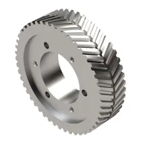
A herringbone gear, also known as a double helical gear, is a type of gear used to transmit power and motion between parallel shafts. It features two opposing rows of helical teeth joined together to form a distinctive V-shaped pattern. This unique tooth arrangement gives the gear its “herringbone” name, as the teeth resemble the skeleton of a herring fish.
Unlike a conventional single helical gear, which generates axial thrust during operation, a herringbone gear combines right-hand and left-hand helix angles on the same gear body. The opposing thrust forces automatically balance each other, eliminating the need for additional thrust bearings. As a result, herringbone gears provide smoother meshing, reduced vibration, lower noise levels, and reliable performance in high-speed and heavy-load transmission systems.
Is a Herringbone Gear the Same as a Double Helical Gear?
A herringbone gear and a double helical gear are closely related gear types and are often treated as the same in industrial discussions. Both designs combine a right-hand helix and a left-hand helix on the same gear body, allowing the axial thrust generated by one helix to counteract the thrust produced by the other. This balanced arrangement eliminates the large axial loads commonly associated with single helical gears.
Historically, the herringbone gear was developed as an improvement over conventional helical gears to solve the problem of excessive axial thrust. Over time, the broader term double helical gear became widely adopted in engineering and manufacturing literature. As a result, many engineers and gear manufacturers use the two terms interchangeably.
However, there is a subtle structural difference between them. A traditional double helical gear typically includes a small center gap or relief groove between the left-hand and right-hand helices. This clearance simplifies manufacturing and assembly. A true herringbone gear, by contrast, features a continuous V-shaped tooth pattern with no center gap, where the two helices meet directly at the center. Although their geometry differs slightly, both gear types deliver nearly identical performance benefits, including reduced vibration, lower noise levels, higher load capacity, and complete cancellation of axial thrust.
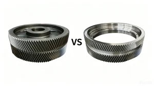
Quick Comparison: Herringbone Gear vs Double Helical Gear
| Feature | Herringbone Gear | Double Helical Gear |
| Tooth Arrangement | Continuous V-shaped teeth | Two opposite helices separated by a center gap |
| Center Clearance | No | Yes |
| Axial Thrust | Fully balanced | Fully balanced |
| Manufacturing Difficulty | Higher | Lower |
| Production Cost | Higher | Moderate |
| Typical Applications | Marine propulsion, heavy industrial drives | Industrial gearboxes, mining equipment, power transmission systems |
| Industry Usage | Traditional term | More commonly used engineering term |
In practice, most engineers focus on the thrust-canceling function rather than the small geometric difference, which is why the terms “herringbone gear” and “double helical gear” are frequently used interchangeably in catalogs, technical documents, and industrial applications.
How Does a Herringbone Gear Work?
A herringbone gear works by canceling axial thrust through its counter-angled teeth. While the left-hand helix creates an axial force in one direction, the right-hand helix creates an equal and opposite force, neutralizing net thrust internally.
The herringbone gear working principle is based on two opposite helical tooth sets machined on the same gear body. One side features left-hand helical teeth, while the other features right-hand helical teeth, forming a continuous V-shaped pattern.
During double helical gear operation, both tooth sets mesh with the mating gear simultaneously. The teeth engage gradually rather than suddenly, ensuring smooth torque transmission, lower noise, and reduced vibration. At the same time, the opposite helix angles generate equal and opposite axial forces, which cancel each other out automatically.
Why Does a Herringbone Gear Eliminate Axial Thrust?
The key reason lies in the direction of the helix angle.
A single helical gear generates axial thrust because its angled teeth create a force component parallel to the shaft. This side force pushes the gear in one direction and must be absorbed by thrust bearings.
In a herringbone gear, the left-hand and right-hand helices generate axial forces of equal magnitude but in opposite directions. Because both tooth sets carry the load simultaneously, these forces balance each other internally.
Single Helical Gear:
- Torque transmission ✓
- Axial thrust generated ✗
- Requires thrust bearings ✗
Herringbone Gear:
- Torque transmission ✓
- Opposing axial forces generated ✓
- Axial thrust automatically canceled ✓
As a result, the net axial force is nearly zero, reducing bearing loads while allowing the gear to transmit higher torque smoothly and efficiently. This self-balancing characteristic is the primary reason herringbone gears are widely used in heavy-duty gearboxes, marine propulsion systems, rolling mills, and other high-power transmission applications.
Advantages of Herringbone Gears
The unique double-helical tooth arrangement gives herringbone gears several advantages over spur gears and single helical gears. By combining left-hand and right-hand helices on the same gear, they achieve smooth power transmission while eliminating axial thrust. These characteristics make them a preferred choice for high-speed, high-load, and heavy-duty industrial applications.
Key Benefits of Herringbone Gears
| Benefit |
Description |
| Zero Axial Thrust | Opposing helices generate equal and opposite axial forces, eliminating the need for large thrust bearings. |
| Smooth Power Transmission | Multiple teeth remain in contact simultaneously, reducing shock loads and ensuring continuous torque transfer. |
| Low Noise and Vibration | Progressive tooth engagement minimizes impact during meshing with quieter operation. |
| High Load Capacity | The large tooth contact area distributes loads more evenly, allowing higher torque transmission. |
| Improved Efficiency | More effective power transfer reduces energy losses and improves overall gearbox performance. |
| Better Heat Distribution | Load sharing across multiple teeth helps reduce localized stress and heat buildup. |
| Longer Service Life | Lower vibration, reduced wear, and balanced loading contribute to extended gear and bearing life. |
| Suitable for High-Speed Applications | Stable operation at high rotational speeds makes them ideal for demanding industrial systems. |
Why Industries Choose Double Helical Gears
One of the major advantages of double helical gears is their ability to combine the smooth running characteristics of helical gears with automatic thrust balancing. Because several teeth are engaged at the same time, loads are distributed over a larger contact area. This can reduce tooth stress and improving durability.
Compared with single helical gears, herringbone gears operate more smoothly at high speeds and under heavy loads. Their balanced design reduces bearing loads as well, helping improve system reliability and service life at the same time.
Although herringbone gears are more complex and costly to manufacture due to their V-shaped tooth geometry, the performance benefits often outweigh the additional production cost. For applications requiring high torque, low vibration, and long-term reliability, they remain one of the most effective gear solutions available.
Applications of Herringbone Gears
Herringbone gear applications are frequently found in heavy-duty power transmission systems due to their high load-carrying capacity, smooth operation, and ability to eliminate axial thrust. They are especially valuable in those industries where equipment operates continuously under high torque and demanding conditions.
Marine Propulsion Systems
Herringbone gears are widely used in marine gearboxes and propulsion systems to transfer power from the engine to the propeller shaft. Their balanced tooth design eliminates axial thrust, reduces bearing loads and improves transmission reliability. The smooth meshing action also helps minimize vibration and noise, which is particularly important for large commercial vessels, naval ships, and offshore equipment.
Mining Equipment
Mining machinery usually need to operate under extreme loads, shock impacts, and harsh environmental conditions. Herringbone gears are commonly used in crushers, conveyors, grinding mills, and heavy-duty drive systems because they can transmit large amounts of torque while maintaining stable operation. Their ability to distribute loads across multiple teeth helps reduce wear and also extend equipment service life.
Steel Rolling Mills
Steel rolling mills require gears capable of handling continuous heavy loads and frequent load fluctuations. Herringbone gears have long been a preferred solution in rolling mill drives since they have high power density and smooth torque transmission. The elimination of axial thrust also helps improve gearbox stability and reduce maintenance requirements in these demanding production environments.
Industrial Gearboxes
Many large industrial gearboxes incorporate herringbone gears to achieve reliable power transmission with minimal vibration. Thus they are easily found in compressors, blowers, pumps, mixers, cement plants, and other heavy industrial machinery. Their high efficiency and excellent load-sharing characteristics make them an ideal option for applications that require continuous operation and long service life.
Power Generation Equipment
Power generation systems, including hydroelectric, thermal, and renewable energy installations, often utilize herringbone gears in speed increasers and reduction gearboxes. These gears provide smooth and efficient power transfer while accommodating high rotational speeds and heavy loads. Their robust design contributes to reliable long-term operation, which is critical for maintaining consistent power output.
The reason for some industries prefer herringbone gear lies in the need for high torque transmission, low vibration, and long-term reliability. By combining the advantages of helical gears with automatic axial thrust cancellation, herringbone gears deliver stable performance in some of the most demanding industrial environments.
Herringbone Gear vs Other Gear Types
Selecting the right gear type depends on factors such as load capacity, operating speed, noise requirements, efficiency, and installation constraints. Compared with spur, helical, bevel, and worm gears, herringbone gears offer a unique combination of high torque capacity, smooth power transmission, low vibration, and automatic axial thrust cancellation. While they are generally more complex and costly to manufacture, their superior performance always makes them a preferred choice for heavy-duty industrial applications where reliability and long service life are critical. The following comparisons highlight the key differences between herringbone gears and other commonly used gear types.
Herringbone Gear vs Helical Gear
At first glance, herringbone gears and helical gears appear very similar because both use angled teeth to achieve smoother meshing than spur gears. In fact, a herringbone gear can be viewed as two mirrored helical gears combined into a single gear body. However, the difference in tooth arrangement leads to significant differences in performance and application.
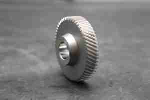
A standard helical gear uses either a left-hand or right-hand helix. While this design provides smooth engagement, lower noise, and higher load capacity than spur gears, it also generates axial thrust during operation. As the helix angle increases, the axial force acting on the bearings increases as well, requiring more robust bearing arrangements to absorb both radial and thrust loads.
A herringbone gear solves this limitation by combining left-hand and right-hand helices on the same gear. The axial force produced by one side is equal and opposite to the force generated by the other side, resulting in automatic thrust cancellation. This allows herringbone gears to transmit higher torque while maintaining excellent operational stability.
Another advantage is that herringbone gears can utilize larger helix angles than conventional helical gears. A larger helix angle increases tooth overlap, improves load sharing, and further reduces vibration and wear. For this reason, herringbone gears are commonly selected for high-power industrial drives where smooth operation and reliability are critical.
The trade-off is manufacturing complexity. Helical gears are relatively straightforward to produce using standard hobbing or shaping processes. Herringbone gears require much tighter alignment and more specialized machining methods, making them more expensive to manufacture.
| Feature | Herringbone Gear | Helical Gear |
| Tooth Design | Double-helical (left-hand + right-hand helices) | Single helical tooth direction |
| Axial Thrust | Virtually eliminated | Significant axial thrust generated |
| Bearing Requirements | Primarily radial-load bearings | Bearings must handle radial and axial loads |
| Load Capacity | Very high | High |
| Torque Transmission | Excellent for heavy-duty applications | Suitable for medium to high loads |
| Noise & Vibration | Very low | Low |
| Typical Helix Angle | Up to about 45° | Typically 15°–25° |
| Manufacturing Complexity | High | Moderate |
| Manufacturing Cost | Higher | Lower |
| Common Applications | Marine propulsion, steel mills, mining equipment, large industrial gearboxes | Automotive transmissions, industrial machinery, pumps, compressors |
Herringbone Gear vs Spur Gear
Both herringbone gears and spur gears are widely used for power transmission, but they are designed for different operating conditions. Spur gears feature straight teeth parallel to the shaft axis, while herringbone gears use a double-helical, V-shaped tooth pattern that balances axial forces automatically.
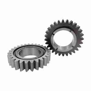 The most significant difference lies in how the teeth engage. Spur gear teeth mesh almost instantly, which can generate more noise and vibration at higher speeds. In contrast, herringbone gear teeth engage gradually along the tooth surface, resulting in smoother operation, lower noise levels, and improved load distribution.
Herringbone gears also offer a clear advantage in heavy-duty applications. Their double-helical design allows multiple teeth to share the load simultaneously while eliminating axial thrust. This makes them well suited for transmitting high torque in large industrial machines. Spur gears, although highly efficient and economical, are generally preferred for moderate-load applications where simplicity and cost are more important than noise reduction.
Another benefit of herringbone gears is improved operational stability. The opposing helix angles help maintain accurate tooth contact and minimize the effects of backlash, contributing to smoother power transmission under varying loads.
| Feature | Herringbone Gear | Spur Gear |
| Tooth Design | Double-helical V-shaped teeth | Straight teeth |
| Axial Thrust | Virtually eliminated | No axial thrust |
| Noise Level | Very low | Higher at high speeds |
| Vibration | Low | Moderate |
| Load Capacity | Very high | Moderate to high |
| Torque Transmission | Excellent for heavy-duty service | Suitable for general applications |
| Backlash Control | Better tooth engagement stability | Depends on gear quality and adjustment |
| Manufacturing Cost | Higher | Lower |
| Typical Applications | Marine drives, rolling mills, mining equipment, industrial gearboxes | Conveyors, machine tools, automotive systems, general machinery |
In general, spur gears are a cost-effective solution for standard power transmission systems, while herringbone gears are preferred when high torque capacity, smooth operation, and low noise are critical requirements.
How Are Herringbone Gears Manufactured?
The quality and performance of a herringbone gear depend heavily on the manufacturing process. Because the gear contains two precisely matched helical tooth sets with opposite helix directions, herringbone gear manufacturing requires tighter tolerances and more advanced machining capabilities than standard spur or helical gears.
A typical manufacturing process includes the following steps: Forging → Rough Machining → Gear Cutting → Heat Treatment → Gear Grinding → Inspection
Manufacturing Process Details
- Forging
High-strength alloy steel such as 20CrMnTi, 18CrNiMo7-6, or 8620 is commonly selected for heavy-duty applications. Forging refines the grain structure and improves the gear’s strength, fatigue resistance, and durability.
- Rough Machining
The forged blank is turned and machined to create the basic gear geometry, including bore dimensions, mounting surfaces, and reference datums for subsequent operations.
- Gear Cutting
The left-hand and right-hand helical teeth are generated with precise control of module, helix angle, pitch, and tooth geometry. This stage is one of the most critical parts of double helical gear machining, as both tooth sections must align perfectly at the center.
- Heat Treatment
Carburizing, quenching, and tempering are commonly used to increase surface hardness while maintaining a tough core. Proper heat treatment significantly improves wear resistance and load-carrying capacity.
- Gear Grinding
For high-precision applications, gear grinding is performed after heat treatment to correct distortions and achieve the required tooth accuracy, surface finish, and contact pattern.
- Inspection
Final quality verification typically includes gear measuring center inspection, CMM measurement, tooth profile and lead analysis, runout inspection, hardness testing, and contact pattern evaluation.
Key Challenges in Herringbone Gear Manufacturing
Producing a high-quality herringbone gear involves several technical challenges that directly affect transmission performance and service life.
V-Groove Alignment
The transition area between the left-hand and right-hand helices must be precisely aligned. Any deviation at the centerline can negatively affect tooth contact, load distribution, and meshing smoothness. Maintaining accurate V-groove alignment is one of the most demanding aspects of herringbone gear production.
Tooth Profile Accuracy
Both helical sections must maintain consistent involute profiles, helix angles, pitch accuracy, and lead geometry. Even small profile deviations can increase noise, vibration, and localized tooth loading, particularly in high-speed applications.
Heat Treatment Distortion
Large herringbone gears are especially susceptible to dimensional changes during carburizing and quenching. Controlling heat treatment distortion is critical to preserving gear geometry and minimizing corrective machining after hardening.
Gear Grinding Precision
Post-heat-treatment grinding requires extremely accurate positioning and synchronization between the two helical sections. High-precision gear grinding ensures optimal tooth contact patterns, reduced transmission error, lower operating noise, and longer service life.
Why Manufacturing Expertise Matters
Compared with standard helical gears, herringbone gears demand significantly higher levels of engineering, machining, heat-treatment control, and inspection capability. The combination of precise tooth alignment, controlled heat treatment, and advanced grinding technology ultimately determines whether a herringbone gear can deliver the smooth operation, high load capacity, and long-term reliability expected in demanding industrial applications. For this reason, choosing an experienced manufacturer with complete in-house production and inspection capabilities is often as important as the gear design itself.
How to Select the Right Herringbone Gear?
Choosing the right herringbone gear requires balancing load requirements, operating conditions, and performance expectations. A proper selection ensures stable operation, long service life, and efficient power transmission in demanding applications.
Key Factors for Choosing a Herringbone Gear
- Torque
Determine the maximum working torque and possible shock loads. High-torque applications (e.g., mining, steel mills, marine drives) require larger modules, wider face width, and stronger alloy steel materials. - Speed
Operating speed affects heat generation, vibration, and precision requirements. High-speed systems need higher accuracy grades and better dynamic balance, while low-speed systems prioritize load capacity. - Material
Common materials include carburized alloy steels such as 20CrMnTi, 8620, and 18CrNiMo7-6. Material choice depends on strength requirements, wear resistance, and service environment. - Precision Grade
Higher precision reduces noise, vibration, and transmission error. Critical applications like power generation or marine gearboxes require tighter tolerances compared to general industrial machinery. - Lubrication
Proper lubrication is essential for reducing friction, controlling temperature, and extending gear life. Oil type and lubrication system should match load, speed, and operating conditions. - Operating Environment
Temperature, humidity, dust, corrosion risk, and duty cycle all influence gear selection. Harsh environments often require enhanced surface treatment or protective design.
When choosing a herringbone gear, it is important to consider the entire transmission system rather than a single parameter. A well-balanced design across torque, speed, material, precision, lubrication, and environment will significantly improve reliability and service life. For high-performance applications, working with an experienced gear manufacturer helps ensure optimal design and stable long-term operation.
Need Custom Herringbone Gears for Your Industrial Gearbox?
Belon manufactures precision herringbone gears and double helical gears for marine, mining, steel, and industrial transmission systems. With advanced CNC machining, heat treatment, gear grinding, and inspection capabilities, we provide professional and reliable custom gear solutions tailored to your specific application requirements. Contact our engineering team today (Email us: marketing@belongear.com) for technical consultation and a fast quotation.
FAQ
Q1: What is a herringbone gear?
A herringbone gear is a specialized type of double helical gear designed for high-load parallel shaft power transmission. Structurally, it consists of two mirrored helical tooth sets (one left-hand and one right-hand helix) integrated side-by-side on a single gear blank. This specific orientation creates a distinct continuous “V” or fishbone pattern across the gear’s face width.
While standard double helical gears often feature a central clearance groove or relief gap between the two helix halves to allow for traditional cutting tools, a true herringbone gear features a continuous tooth trace with no central gap, meeting precisely at an apex. This complex geometry provides the ultimate combination of smooth mechanical engagement and self-balancing force distribution, though it requires advanced manufacturing processes like Sykes gear shaping or multi-axis CNC milling to produce.
Q2: How does a herringbone gear work?
A herringbone gear operates on the principle of progressive, gradual tooth engagement combined with opposing vector force cancellation.
- Gradual Meshing: Unlike standard spur gears where entire teeth engage all at once, the V-shaped teeth of a herringbone gear roll into mesh progressively from one end to the other. At any given moment, multiple teeth are overlapping in engagement (achieving a very high contact ratio), which ensures seamless torque transfer and a significant reduction in operating vibration and noise.
- Axial Thrust Cancellation: In a single helical gear, the helix angle inherently generates an axial (sideway) thrust force along the shaft, requiring heavy-duty thrust bearings to prevent displacement. A herringbone gear solves this by placing two opposite helix angles against each other. When torque is applied, the left-hand helix generates an axial force in one direction, while the right-hand helix generates an equal and opposite force. These two internal forces directly counteract and cancel each other out within the gear blank itself.
Technical Note: For a herringbone gear to work perfectly, precise axial alignment is critical. If there is a mounting offset or shaft deflection, the load sharing between the two helix halves becomes uneven, which can result in residual thrust and localized tooth wear.
Q3: Why are herringbone gears used in heavy-duty machinery?
Herringbone gears are the gold standard for heavy-duty, continuous-running industrial machinery due to three critical engineering advantages:
- Extreme Load and Torque Capacity: Because of the V-shaped configuration, the effective contact area per tooth is vastly larger than that of a spur or single helical gear of identical width. This allows the gear set to distribute immense shocks and heavy structural loads across multiple contact points simultaneously.
- Elimination of Thrust-Induced Bearing Wear: In heavy sectors like mining, steel rolling mills, and cement production, the torque required is massive. Using single helical gears at this scale would create catastrophic axial thrust, destroying bearings rapidly. Herringbone gears cancel this force internally, dramatically extending the service life of the entire drivetrain.
- Unmatched Reliability in High-Vibration Environments: Heavy machinery often operates under variable, harsh conditions (e.g., industrial pumps, marine propulsion, and heavy-duty crushers). The continuous, smooth rolling engagement prevents severe torque spikes, minimizes back-and-forth shaft movement, and prevents catastrophic tooth shearing under sudden load shifts.
Q4: Are herringbone gears more efficient than spur gears?
From a purely mechanical power-transmission standpoint, herringbone gears and spur gears are both highly efficient, typically operating in the 97% to 99% efficiency range under optimal lubrication. However, when evaluating system-wide operational efficiency under high loads, herringbone gears offer distinct advantages:
- Overcoming Spur Gear Limitations: Spur gears suffer from instantaneous tooth-to-tooth contact, which creates high friction peaks, severe impact stresses, and loud whining noises at higher speeds. They are highly inefficient at managing high-velocity, high-torque demands due to rapid wear and energy loss through vibration.
- Reduction in System Friction: While the sliding friction of a herringbone’s angled teeth is marginally higher than the pure rolling friction of a spur gear, a herringbone system eliminates the need for heavy thrust bearings. Thrust bearings inherently generate significant frictional drag under load. By eliminating this auxiliary component friction, the total gearbox system efficiency of a herringbone drive under heavy duty conditions is vastly superior, resulting in lower operating temperatures and reduced energy consumption over long duty cycles.
Q5: Where are herringbone gears used?
Herringbone gears are preferred in heavy-duty, high-torque industrial transmissions and high-speed systems where standard gears fail due to noise, vibration, or extreme axial thrust. By canceling out internal axial forces ($0$ net thrust), they eliminate the need for bulky thrust bearings, making them critical for five major industrial sectors:
1. Mining & Cement Processing (High Impact)
- Ball Mills & SAG Mills:Transmit immense torque required to grind thousands of tons of rock and ore.
- Heavy-Duty Crushers:The multiple-tooth engagement absorbs violent torque spikes and prevents tooth shearing when crushing large materials.
2. Steel Rolling Mills (Ultra-High Torque)
- Drive Rollers:Deliver continuous, massive torque to squeeze solid metal billets. The balanced design prevents shaft deflection, ensuring precise and uniform steel thickness.
3. Marine Propulsion (High Reliability)
- Main Marine Gearboxes:Transfer thousands of horsepower from ship engines to propellers. They maximize power density within a compact, lightweight housing layout.
- Steering Systems:Provide high-precision rudder control while absorbing unpredictable wave impact forces.
4. Oil & Gas Production (Continuous Operation)
- High-Pressure Mud Pumps:Smooth out severe pressure fluctuations during oil drilling, extending equipment runtime.
- Centrifugal Compressors:Eliminate high-speed bearing friction and heat buildup, lowering energy consumption.
5. Aerospace & Power Generation (Weight & Noise Reduction)
- Helicopter Main Rotors:Eliminating thrust bearings saves critical aircraft weight and increases power density.
- Turbine Generators: The continuous rolling tooth transition reduces high-frequency mechanical whine by up to 20dB, ensuring quieter plant operations.
Q6: Are herringbone gears quiet?
Yes, herringbone gears are exceptionally quiet.
Their whisper-quiet operation is driven by two main factors:
-
Smooth Tooth Engagement: Unlike spur gears that clap together all at once, the angled “V” shape teeth mesh gradually and progressively. This minimizes impact shocks, eliminates high-frequency whine, and reduces noise by up to 20 dB compared to spur gears.
-
Zero Axial Thrust: The opposing helix angles cancel out sideways forces internally. With no axial thrust pushing against the bearings, the gears run with minimal friction, vibration, and secondary mechanical noise.
The Bottom Line: They are the gold standard for high-speed, heavy-load applications (like marine propulsion and turbines) where silencing severe vibration and noise is critical.