

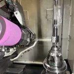
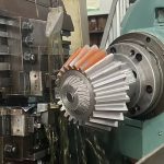
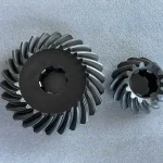
Abstract: A worm drive is an efficient solution for high-ratio speed reduction and right-angle power transmission. This guide covers its working principle, key components, advantages, limitations, applications, selection considerations, maintenance, and the manufacturing technologies that determine performance and service life.
What Is a Worm Drive?
A worm drive is a mechanical power transmission system that transfers motion and torque between two non-parallel, non-intersecting shafts, typically arranged at a 90° angle. It consists of a threaded worm that meshes with a worm wheel, enabling large speed reductions and significant torque multiplication within a compact assembly.
Definition of a Worm Drive
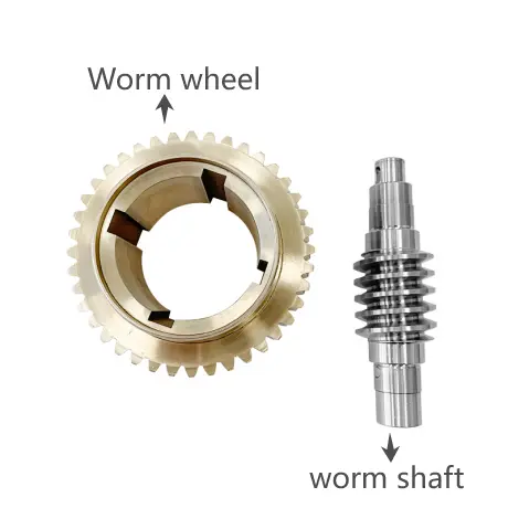 A worm drive is a gear transmission mechanism composed of a screw-shaped worm and a mating worm wheel. As the worm rotates, its helical thread drives the teeth of the worm wheel, reducing rotational speed while increasing output torque. Since the two components operate on perpendicular axes, worm drives are widely used wherever compact right-angle transmission is required.
From an engineering perspective, worm drives belong to the broader family of helicoidal surface drives, sharing geometric characteristics with power screws and other screw-based transmission systems. Their performance depends not only on the gear ratio but also on factors such as tooth geometry, lubrication conditions, material pairing, and manufacturing precision. These factors collectively determine efficiency, wear resistance, and service life.
Worm Drive vs. Worm Gearbox
The terms worm drive and worm gearbox are often used interchangeably, but they actually refer to different concepts.
- A worm drive specifically describes the gear transmission mechanism formed by the worm and worm wheel. It focuses on the meshing principle between the worm wheel and worm shaft.
- A worm gearbox, on the other hand, is the complete mechanical assembly that houses the worm drive along with supporting components such as bearings, shafts, seals, lubrication systems, and the gearbox housing. In other words, the worm drive is the transmission element inside the worm gearbox.
| Worm Drive | Worm Gearbox |
| Worm and worm wheel transmission mechanism | Complete enclosed gear reducer |
| Describes the operating principle | Describes the finished transmission unit |
| Includes the worm and worm wheel | Includes gears, housing, bearings, shafts, seals, and lubricant |
| Focuses on motion and torque transmission | Focuses on delivering power in industrial applications |
Understanding this distinction is important when selecting industrial equipment. Engineers typically evaluate the performance of the worm drive, while machine builders and purchasers usually specify a complete worm gearbox based on torque, reduction ratio, mounting configuration, and operating conditions.
Main Components of a Worm Drive
A worm drive consists of two primary transmission elements supported by several auxiliary components.
Worm
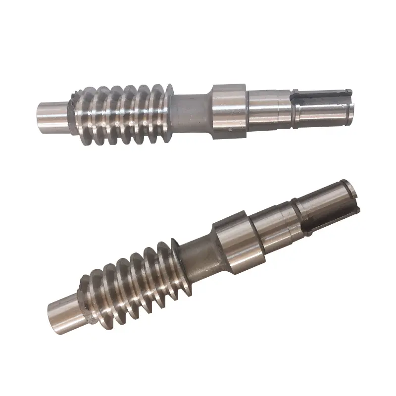
The worm is the driving member of the gear pair. It resembles a precision-machined screw with one or more helical threads wrapped around its cylindrical surface. During operation, the worm is usually connected directly to the motor input shaft, transmitting rotational motion to the worm wheel through continuous tooth engagement.
Worm Wheel
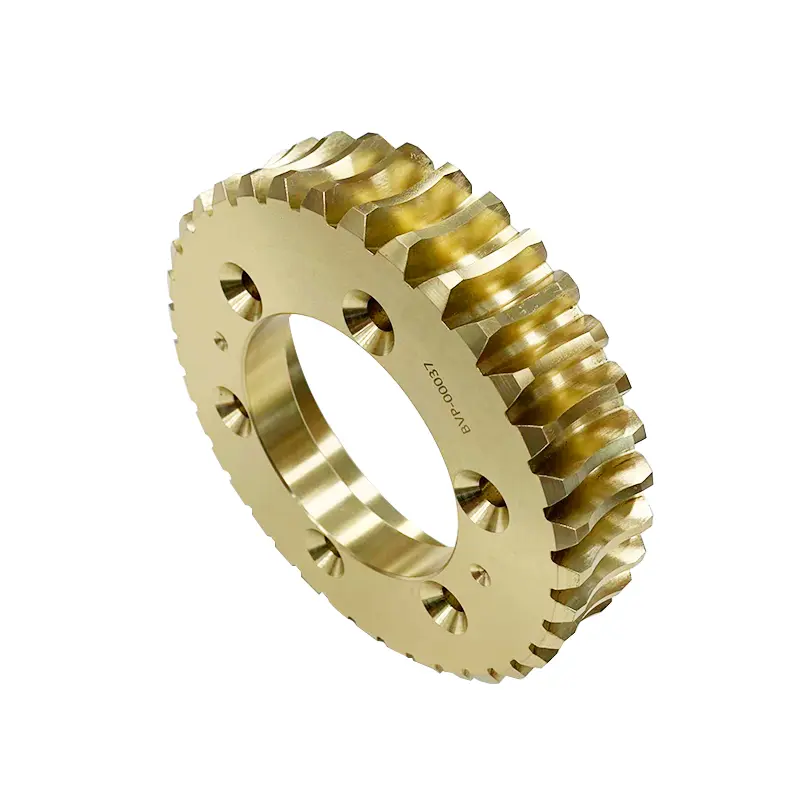
The worm wheel is the driven gear that meshes with the worm. Because the contact between the two components involves substantial sliding, worm wheels are commonly manufactured from bronze or other wear-resistant materials, while the worm is typically made from hardened alloy steel.
Shafts and Bearings
Input and output shafts transfer power into and out of the gearbox, while high-quality bearings support both the worm and worm wheel, maintaining accurate alignment under radial and axial loads.
Housing and Lubrication System
The gearbox housing maintains the correct center distance between the worm and worm wheel while protecting internal components from contamination. Since worm drives rely heavily on sliding contact, an effective lubrication system is essential for minimizing friction, controlling operating temperature, and reducing wear.
How Does a Worm Drive Work?
A worm drive transmits power via the continuous meshing process of worm and worm wheel.
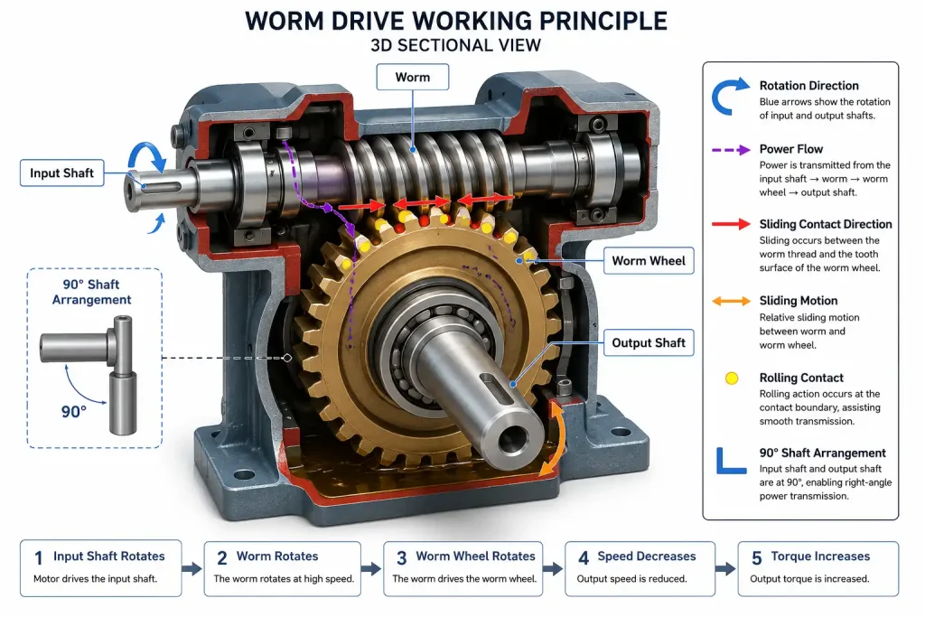
When the input shaft rotates, the worm’s helical thread engages the teeth of the worm wheel. Each revolution of the worm advances the worm wheel by only a limited number of teeth, depending on the worm’s number of starts. This gradual engagement reduces output speed while proportionally increasing output torque.
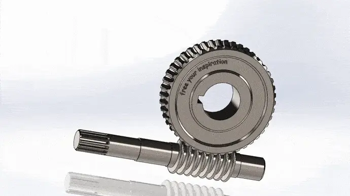
The performance of a worm drive depends not only on its reduction ratio but also on factors such as worm geometry, lead angle, tooth contact conditions, lubrication quality, and manufacturing accuracy. Together, these factors determine transmission efficiency, load capacity, operating temperature, and service life.
Worm and Worm Wheel Meshing
The operating principle of a worm drive begins with the interaction between the worm and worm wheel gear. The worm functions as the driving element, while the worm wheel acts as the driven gear. As the worm rotates, its helical thread continuously engages successive teeth on the worm wheel, creating a smooth and uninterrupted transfer of motion.
Usually, the contact between a worm and a worm wheel follows a helical path across the tooth surface. This continuous meshing increases the contact area and allows multiple teeth to share the transmitted load simultaneously.
Sliding Motion and Torque Transmission
One of the defining characteristics of a worm drive is that power is transmitted through a combination of rolling and sliding contact. As the worm thread moves across the worm wheel teeth, a significant sliding motion occurs along the tooth surfaces. This sliding action distinguishes worm drives from most other gear systems and directly influences their operating characteristics.
The sliding contact offers several advantages. It enables exceptionally smooth and quiet operation, supports high reduction ratios within a compact gearbox, and allows the worm drive to produce substantial torque multiplication. In many applications, the friction generated by this sliding motion can also provide a degree of self-locking, preventing the output shaft from driving the input shaft under specific operating conditions.
However, sliding contact also increases friction and heat generation. For this reason, lubrication becomes one of the most critical factors affecting efficiency, wear resistance, and gearbox longevity.
Gear Reduction Principle
The speed reduction capability of a worm drive results from the relationship between the worm’s threads (known as starts) and the number of teeth on the worm wheel.
Each complete revolution of the worm advances the worm wheel by only the number of teeth corresponding to the worm’s starts. For example, a single-start worm rotates the worm wheel by one tooth for every revolution, while a two-start worm advances it by two teeth. Because the worm wheel usually contains many more teeth than the worm has starts, the output shaft rotates much more slowly than the input shaft.
The transmission ratio can therefore be expressed as:
Gear Ratio=Number of Starts on Worm / Number of Teeth on Worm Wheel
This simple relationship enables worm drives to achieve reduction ratios ranging from approximately 5:1 to well over 100:1 in a single stage, eliminating the need for multiple gear sets in many applications. Higher reduction ratios result in lower output speed and greater torque multiplication, making worm drives particularly suitable for conveyors, hoists, rotary indexing tables, packaging machinery, and other equipment requiring controlled, high-torque motion.
Key Components of a Worm Gearbox
A worm gearbox is more than just a worm and wheel gear. It is a complete transmission assembly designed to deliver smooth, reliable, and efficient power transfer under demanding operating conditions. Every component—from the worm shaft and worm wheel to the bearings, housing, and lubrication system—plays a critical role in ensuring transmission accuracy, load capacity, thermal stability, and service life.
While the worm and worm wheel perform the actual speed reduction, supporting components maintain precise alignment, reduce friction, dissipate heat, and protect the gear set from contamination.
Worm Shaft
The worm shaft is the driving element of the gearbox. It combines the functions of a transmission shaft and a precision-machined helical gear, transferring rotational power directly from the motor to the worm wheel.
Depending on the application, worm shafts may be manufactured with single-start or multi-start threads. A single-start worm typically provides higher reduction ratios and stronger self-locking characteristics, while multi-start worms offer improved transmission efficiency and higher output speed.
Because the worm remains in continuous sliding contact with the worm wheel, its tooth profile and surface quality have a significant influence on gearbox performance. Modern worm shafts are produced using highly accurate machining and grinding processes to achieve precise tooth geometry and favorable contact conditions. Accurate lead geometry and profile accuracy can distribute loads evenly across the tooth surface, reducing localized stress and improving transmission stability.
Worm Wheel
The worm wheel is the driven gear that works with the worm shaft and converts the worm’s high-speed rotation into lower-speed, higher-torque output.
Worm wheel operates under continuous sliding conditions. For this reason, material selection is especially important. Combining a hardened steel worm with a bronze worm wheel creates a favorable tribological pair. Bronze provides excellent conformability and anti-seizure characteristics, while hardened steel offers the strength needed to withstand repeated contact stresses. Together, this combination reduces friction, promotes stable lubrication, and extends gearbox service life.
The geometry of the worm wheel is equally critical. Tooth profile accuracy, surface finish, and proper meshing all influence load distribution and transmission efficiency. Poor contact patterns can lead to excessive localized stress, accelerated wear, and increased operating temperatures.
Modern industrial worm wheels are therefore manufactured with tight dimensional tolerances and carefully inspected in order to ensure consistent tooth engagement throughout the gearbox’s operating life.
Bearings and Housing
Although the worm and worm wheel perform the transmission, bearings and housing provide the structural foundation for a complete gearbox to operate accurately and reliably.
Bearings
The worm shaft is subjected to both radial and axial (thrust) loads because of its helical geometry. Bearings must therefore maintain accurate shaft positioning and resist these combined forces throughout continuous operation.
Proper bearing support helps to:
- Maintain correct gear alignment
- Preserve the designed contact pattern
- Reduce vibration and noise
- Minimize shaft deflection
- Improve gearbox reliability
Housing
The gearbox housing performs far more than a protective function. It accurately positions the worm shaft and worm wheel, maintains the designed center distance, supports the bearing system, and retains the lubricant.
A rigid housing minimizes deformation under load, ensuring that the gear mesh remains consistent even during high-torque operation. It also helps dissipate heat generated by sliding contact while protecting internal components from dust, moisture, and other contaminants.
For industrial gearboxes, cast iron and ductile iron housings are commonly selected because they provide excellent stiffness, vibration damping, and dimensional stability.
Lubrication System
Lubrication is one of the most critical factors influencing the efficiency and service life of a worm gearbox. Without a stable lubricating oil film, friction increases rapidly, causing excessive heat generation, accelerated wear, and potential surface damage.
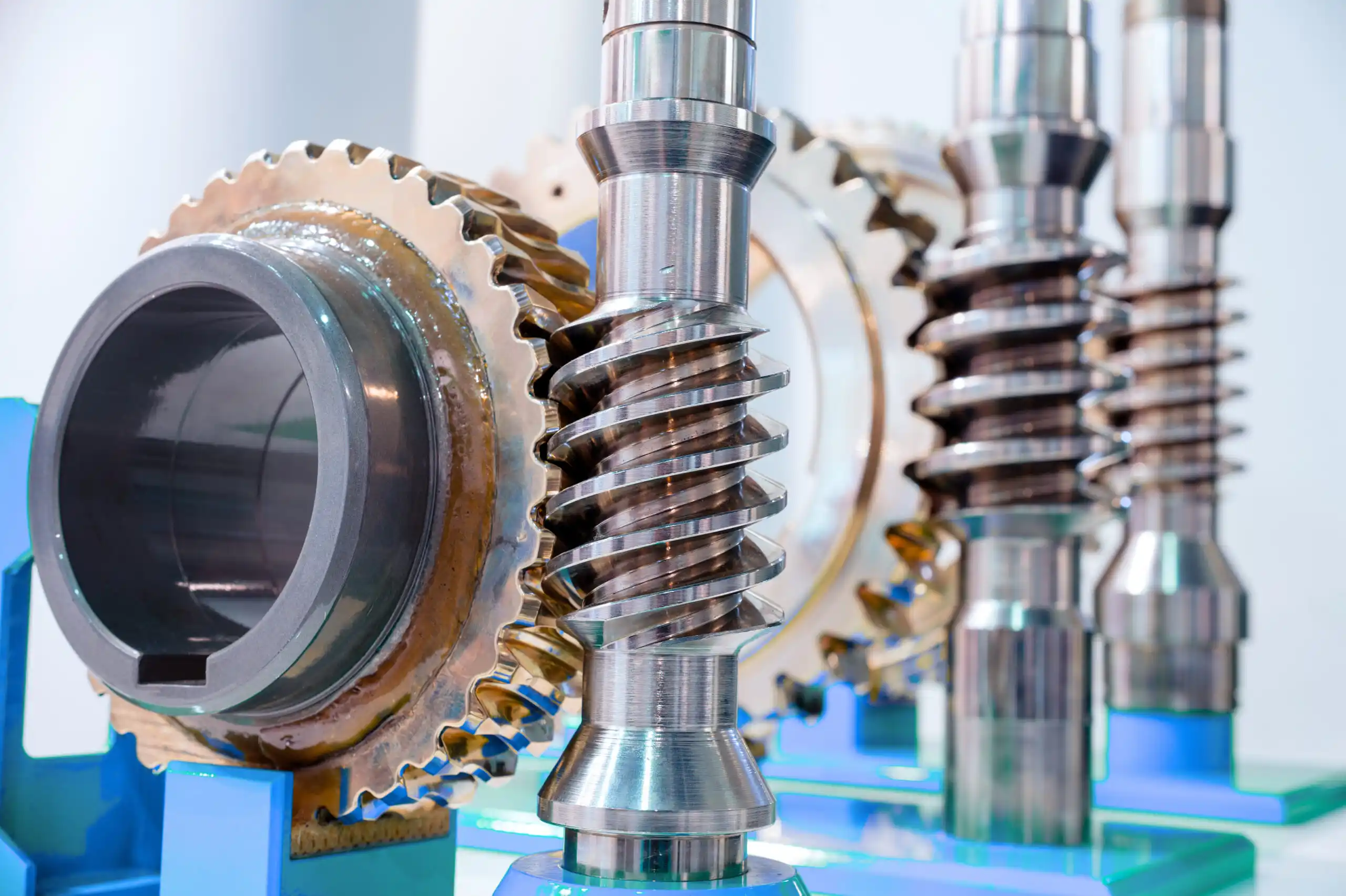
The development of enclosed oil lubrication systems is one of the major milestones that enabled modern worm gearboxes to become practical for industrial applications.
When selecting a lubricant, engineers should consider:
- Operating speed
- Load conditions
- Ambient temperature
- Duty cycle
- Lubricant viscosity
- Material combination of the worm and worm wheel
Routine oil inspection and replacement are equally important at any time.
Advantages of Worm Drives
Worm drives remain one of the most widely used gear transmission systems for industrial machinery given that they combine high reduction ratios, compact construction, smooth operation, and excellent torque transmission within a single-stage gearbox. Although sliding contact results in lower efficiency than some other gear types, continuous improvements in gear geometry, lubrication, and precision manufacturing have significantly enhanced the performance and reliability of modern worm gearboxes.
The following advantages explain why worm drives continue to be the preferred solution for conveyors, lifting equipment, rotary tables, packaging machines, gate actuators, and many other industrial applications.
High Reduction Ratio
One of the greatest advantages of a worm drive is its ability to achieve very high speed reduction in a single gear stage. A worm gearbox can provide substantial speed reduction using only one worm and one worm wheel compared with spur or helical gear systems.
As mentioned above, the reduction ratio is determined by the relationship between the number of starts on the worm and the number of teeth on the worm wheel. Since each revolution of the worm advances the worm wheel by only a small number of teeth, the output shaft rotates much more slowly than the input shaft while delivering considerably higher torque.
Typical Benefits
- High reduction ratios in a single stage
- Simplified gearbox design
- Fewer transmission components
- Lower installation space requirements
- Reduced maintenance complexity
Compact Right-Angle Design
Worm drives naturally transmit power between two non-parallel shafts positioned at approximately 90 degrees, which means they will be an excellent choice for applications with limited installation space.
Because of the perpendicular arrangement of the worm and wheel to one another, the gearbox supplies efficient right-angle power transmission without requiring additional bevel gears or complex shaft arrangements. This compact layout allows machine designers to reduce overall equipment size while maintaining high output torque.
The growing demand for compact transmission systems during the electric motor era was one of the major factors driving the widespread adoption of worm gearboxes in industrial machinery.
Today, this space-saving configuration is widely used in:
- Conveyor systems
- Material handling equipment
- Packaging machinery
- Lifting devices
- Automated production lines
- Rotary positioning equipment
Smooth and Quiet Operation
Compared with many conventional gear systems, worm drives are well known for their smooth, stable, and low-noise operation.
This characteristic results from the continuous engagement between the worm thread and the worm wheel teeth. Instead of repeated impact as individual teeth enter and leave mesh, the worm gradually slides across the tooth surface, producing a more uniform transfer of motion. The larger contact area is also good for helping distribute transmitted loads more evenly, reducing vibration and minimizing sudden load fluctuations.
Thanks to modern manufacturing techniques, this performance is further improved.
As a result, worm drives are frequently selected for equipment operating in environments where low noise and smooth motion are essential, such as food processing machines, medical equipment, stage machinery, and automated production systems.
High Torque Output
A worm drive is highly effective at converting high-speed, low-torque input into low-speed, high-torque output.
As rotational speed decreases through the gear reduction process, the available output torque increases proportionally, allowing relatively small electric motors to drive heavy mechanical loads. This function of worm gearboxes makes them particularly suitable for applications requiring controlled movement under high load conditions.
Typical high-torque applications include:
- Hoists and winches
- Conveyor drives
- Rotary tables
- Industrial mixers
- Gate operators
- Packaging equipment
Self-Locking Capability
One of the most distinctive characteristics of certain worm drives is their self-locking capability.
Under appropriate design conditions, the worm can easily drive the worm wheel, while the worm wheel cannot rotate the worm in the opposite direction. This one-way transmission characteristic is primarily influenced by factors such as lead angle, friction conditions, and lubrication.
Self-locking provides an important safety advantage because it can prevent back-driving when the driving motor stops. However, self-locking is not a universal property of all worm drives. Modern high-efficiency worm gearboxes with larger lead angles or optimized lubrication may permit reverse driving under certain operating conditions. Therefore, engineers should evaluate gearbox geometry and operating requirements carefully rather than assuming every worm gearbox is inherently self-locking.
Limitations of Worm Drives
Despite their many advantages, worm drives are not the ideal solution for every power transmission application. Their unique operating principle relies on significant sliding contact between the worm and the worm wheel, which inevitably introduces higher friction than rolling-contact gear systems like spur or helical gears.
This friction affects transmission efficiency, increases operating temperature, and places greater demands on lubrication and material selection. Although worm gear drives have several inherent limitations, most of them can be significantly reduced through proper gear design, material selection, lubrication, precision manufacturing, and regular maintenance. Currently, modern engineering solutions have enabled worm gearboxes to achieve higher efficiency, greater reliability, and longer service life than ever before.
Lower Efficiency
Compared with spur, helical, or bevel gears, worm drives generally operate with lower mechanical efficiency because power is transmitted through continuous sliding contact rather than predominantly rolling contact.
As the worm rotates, its helical thread slides across the worm wheel teeth. Part of the input energy is therefore converted into frictional heat instead of useful mechanical output. The amount of efficiency loss depends on several engineering factors, including:
- Lead angle
- Gear ratio
- Sliding velocity
- Surface finish
- Lubrication quality
- Material pairing
- Manufacturing accuracy
Higher-ratio worm gearboxes usually experience greater sliding action and therefore lower efficiency than lower-ratio designs.
Heat Generation
Unavoidable sliding friction during operation makes worm drives naturally generate more heat than many other gear types.
When input speed or transmitted load increases, friction between the worm and worm wheel also rises, causing the gearbox temperature to increase. If this heat cannot be dissipated effectively, elevated operating temperatures may:
- Accelerate lubricant degradation
- Reduce transmission efficiency
- Increase tooth wear
- Shorten bearing life
- Lower overall gearbox reliability
In high-duty industrial applications, gearbox housings are often designed with sufficient thermal capacity, and larger units may incorporate cooling fins, forced-air cooling, or oil circulation systems to maintain stable operating temperatures.
Lubrication Requirements
Among all gear transmission systems, worm drives place some of the highest demands on lubrication.
The continuous sliding action between the worm and worm wheel requires a stable lubricating oil film to separate the contacting surfaces. Without adequate lubrication, direct metal-to-metal contact can occur, leading to excessive friction, scuffing, accelerated wear, and even gear failure.
Effective lubrication performs several essential functions:
- Reduces sliding friction
- Carries away heat
- Protects tooth surfaces
- Minimizes wear
- Prevents corrosion
- Extends gearbox service life
Wear of Bronze Gear
The worm wheel is commonly manufactured from bronze, while the worm is typically made from hardened alloy steel. This material pairing provides excellent anti-seizure characteristics and promotes stable lubrication, making it one of the most widely adopted combinations for industrial worm drives.
However, because bronze is intentionally the softer material, it experiences gradual wear during long-term operation. This controlled wear protects the hardened steel worm from severe damage and helps maintain reliable meshing under continuous sliding conditions.
Bronze gear wear can be accelerated by several factors, including:
- Inadequate lubrication
- Lubricant contamination
- Excessive operating temperature
- Misalignment
- Overloading
- Poor tooth contact caused by inaccurate manufacturing or assembly
Types of Worm Drives
Worm drives are available in several designs, each developed to meet different requirements for load capacity, efficiency, manufacturing complexity, and service life. While all worm drives operate on the same basic principle, differences in tooth geometry and contact characteristics significantly influence their performance.
Industrial worm drives are typically classified into two major families: cylindrical worm drives and double-enveloping (globoid) worm drives.
- Cylindrical designs are the most common because they are easier to manufacture and suitable for a wide range of industrial applications.
- Double-enveloping worm drives, by contrast, are designed to increase the contact area between the worm wheel and the worm shaft, allowing substantially higher load capacity and improved transmission performance under heavy-duty conditions.
Another important classification is based on the number of worm threads, commonly referred to as starts. Single-start and multi-start worms provide different combinations of reduction ratio, efficiency, and self-locking characteristics, enabling engineers to select the most appropriate design for each application.
Cylindrical Worm Drive
The cylindrical worm drive is the most widely used type in modern machinery and forms the basis of most commercial worm gearboxes. In this design, the worm has a cylindrical body with a helical thread that meshes with a corresponding worm wheel.
Cylindrical worms are relatively straightforward to machine, inspect, and assemble, so they offer an excellent balance between manufacturing cost, reliability, and performance.
Cylindrical worm drives are not a single design but include several different tooth-profile systems, including:
- Archimedean worm
- Involute worm
- Convolute worm
- Circular-profile (CAVEX) worm
- Cone-generated worm
Each profile has different contact characteristics and manufacturing methods and allows designers to optimize transmission performance for specific operating conditions.
Double-Enveloping Worm Drive
A double-enveloping worm drive, also known as a globoid worm drive, is designed so that both the worm and the worm wheel partially wrap around each other. This geometry creates a much larger contact area than a conventional cylindrical worm drive.
Instead of transmitting load through a relatively small contact zone, multiple teeth engage simultaneously over a broader surface. The result is more uniform load distribution, lower contact stress, and higher load-carrying capacity.
The increased contact area improves transmission performance under heavy-duty operating conditions and makes double-enveloping worm drives particularly suitable for applications requiring high torque and long service life.
Double-enveloping worm drives are commonly selected for:
- Heavy-duty lifting equipment
- Mining machinery
- Steel mill drives
- Rotary kilns
- Large indexing tables
- Marine winches
Single-Start Worm
A single-start worm has one continuous helical thread wrapped around the worm shaft.
Because the worm wheel advances by only one tooth for each revolution of the worm, single-start designs provide high reduction ratios and excellent torque multiplication. They also generate relatively high sliding friction, which can contribute to self-locking under appropriate lead angles and operating conditions.
These characteristics make single-start worms well suited for:
- Hoists
- Screw jacks
- Gate actuators
- Positioning mechanisms
- Valve operators
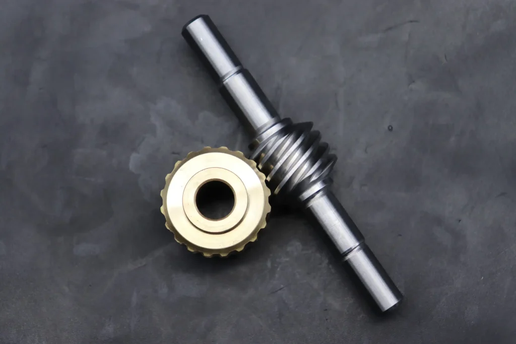
Screw jack worm gear
A screw jack used for lifting industrial equipment typically requires the load to remain stationary after the motor stops. A single-start worm provides the high reduction ratio and favorable self-locking characteristics needed for this application, helping prevent unintended reverse motion.
Multi-Start Worm
A multi-start worm incorporates two or more helical threads, enabling the worm wheel to advance multiple teeth during each revolution.
Compared with single-start designs, multi-start worms generally provide:
- Higher transmission efficiency
- Higher output speed
- Lower reduction ratios
- Reduced sliding distance per transmitted revolution
These characteristics make them suitable for applications where efficiency and continuous operation are more important than maximum reduction ratio.
Typical examples include:
- Conveyor systems
- Industrial mixers
- Packaging machinery
- Automation equipment
- Continuous production lines
Common Materials Used in Worm Drives
Material selection is one of the most important factors affecting the performance, efficiency, and service life of a worm drive. Worm drives operate under continuous sliding contact, placing higher demands on wear resistance, fatigue strength, friction characteristics, and lubrication compatibility.
Rather than relying on a single high-strength material, modern worm drives typically combine a hardened steel worm with a bronze worm wheel to create a tribological pair that balances durability with wear resistance. The gearbox housing must also provide sufficient rigidity and thermal stability to maintain accurate gear alignment under load.
Please note that material performance cannot be separated from manufacturing quality. Heat treatment, precision machining, grinding, and inspection all contribute directly to gearbox reliability and long-term operating performance.
Steel Worms
The worm is typically manufactured from alloy steel because in real life it must withstand repeated contact stresses and continuous sliding against the worm wheel.
Industrial worm shafts commonly use carburizing steels such as 20CrMnTi, 18CrNiMo7-6, 16MnCr5, or AISI 8620, depending on load requirements and regional standards.
After machining, the worm generally undergoes carburizing and quenching to create a hard, wear-resistant surface while maintaining a tough core capable of absorbing shock loads.
This combination provides several important advantages:
- High surface hardness
- Excellent wear resistance
- Improved fatigue strength
- Better resistance to pitting
- Long operating life under heavy loads
The durability of the worm depends not only on material selection but also on manufacturing precision and the resulting tooth contact conditions.
Bronze Worm Wheels
The worm wheel is commonly produced from bronze because its excellent anti-friction properties complement the hardened steel worm.
Rather than maximizing hardness, engineers intentionally select bronze because it offers:
- Good sliding characteristics
- High seizure resistance
- Excellent compatibility with lubricating oil
- Controlled wear that protects the hardened steel worm
- Good conformability during tooth meshing
The hardened steel–bronze material combination has become the industry standard because it reduces friction while promoting stable lubrication and reliable long-term operation.
BELON manufactures worm wheels using carefully selected bronze alloys combined with precision machining and contact pattern verification to ensure uniform load distribution and smooth meshing.
Cast Iron Housing
Although often overlooked, the gearbox housing is a critical structural component that directly affects transmission accuracy and operating stability.
Most industrial worm gearboxes use gray cast iron or ductile iron housings because these materials provide:
- High structural rigidity
- Excellent vibration damping
- Good dimensional stability
- Effective heat dissipation
- Long-term durability
A rigid housing helps maintain the designed center distance between the worm and worm wheel, preserving the intended contact pattern even under heavy loads.
Heat Treatment Methods
Heat treatment matters when determining the strength and durability of worm drive components.
For steel worms, carburizing and quenching remain the most widely adopted processes because they create a hard, wear-resistant case while preserving a tough, impact-resistant core.
A typical manufacturing sequence includes:
- Rough machining
- Carburizing
- Quenching
- Tempering
- Precision grinding
- Final inspection
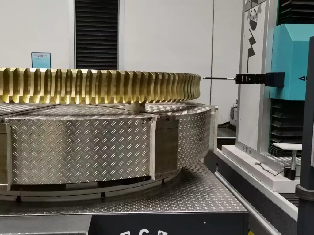
Worm wheel inspection
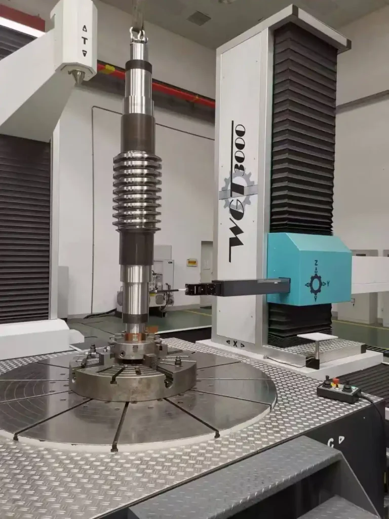
Worm shaft inspection
After heat treatment, the worm is usually ground to restore tooth profile accuracy and achieve the surface finish required for smooth meshing. Precision grinding also improves contact accuracy, helping distribute loads more evenly across the tooth surface.
For applications requiring extremely smooth and quiet operation, lapping may be performed after grinding to further refine the tooth surfaces and optimize the contact pattern.
At BELON, the performance of every worm drive is built on precision manufacturing rather than materials alone. By integrating controlled carburizing, precision grinding, optional gear lapping, and comprehensive inspection throughout the production process, we ensure accurate gear geometry, optimized tooth contact, and consistent product quality. If you would like to custom your gear manufacturing process, let us know your specific gear request.
Typical Applications of Worm Gearboxes
Thanks to their compact structure, high reduction ratios, and excellent torque multiplication, worm gearboxes are widely used across industries which need reliable right-angle power transmission.
Common Industrial Applications
Conveyor Systems
Conveyors require continuous, reliable torque transmission while maintaining stable output speed. Worm gearboxes provide high reduction ratios within a compact footprint, ideal for belt conveyors, roller conveyors, and material handling systems.
Typical equipment
- Belt conveyors
- Roller conveyors
- Bucket elevators
- Warehouse logistics systems
Food & Packaging Machinery
Packaging equipment often operates around the clock in environments where low noise, smooth motion, and precise positioning are essential.
The gradual meshing characteristics of worm gears minimize vibration and provide stable motion, improving packaging accuracy while reducing machine noise.
Typical equipment
- Carton sealing machines
- Filling equipment
- Packaging conveyors
- Labeling systems
Mining Equipment
Mining machinery frequently operates under heavy shock loads and dusty environments.
Worm gearboxes are commonly selected for auxiliary drives, crushers, feeders, and conveying systems because they deliver large torque multiplication while maintaining robust operation.
Typical equipment
- Crushers
- Feeders
- Ore conveyors
- Screening machines
Robotics and Rotary Positioning
Many automation systems require compact right-angle transmissions capable of accurate positioning.
Worm gearboxes are widely used in rotary tables, indexing mechanisms, and robotic positioning systems where smooth rotation and compact dimensions are priorities.
Typical equipment
- Rotary tables
- Indexing systems
- Positioning mechanisms
- Assembly automation
Marine Equipment
Marine applications demand robust gearboxes capable of operating reliably under varying loads and harsh environmental conditions.
For equipment such as anchor winches, mooring systems, and deck machinery, worm gearboxes provide high torque output and, in suitable designs, self-locking characteristics that help prevent unintended reverse motion.
Typical equipment
- Anchor winches
- Mooring winches
- Deck lifting equipment
- Steering auxiliaries
Agricultural Machinery
Agricultural equipment often works under fluctuating loads and dusty operating conditions while requiring dependable power transmission with minimal maintenance.
Worm gearboxes are commonly found in feed mixers, grain conveyors, fertilizer spreaders, and irrigation equipment.
Typical equipment
- Feed mixers
- Grain conveyors
- Fertilizer spreaders
- Irrigation drives
Lifting Equipment
Safety is one of the primary considerations in lifting systems.
Single-start worm drives can provide self-locking characteristics under appropriate operating conditions, helping prevent load back-driving after the motor stops. This makes worm gearboxes suitable for many lifting and positioning applications, although additional braking systems may still be required depending on applicable safety standards.
Typical equipment
- Hoists
- Screw jacks
- Lift platforms
- Material elevators
Industrial Automation
Modern automated production lines require precise, repeatable motion while minimizing machine footprint.
Because worm gearboxes combine compact dimensions with stable speed reduction, they are widely used in positioning devices, inspection equipment, and automated assembly systems.
Typical equipment
- Positioning systems
- Automated assembly lines
- Inspection equipment
- Servo-driven mechanisms
Application Selection Guide
Different industries prioritize different performance characteristics. Selecting the right worm gearbox therefore requires matching gearbox features to application requirements rather than focusing on reduction ratio alone.
| Industry | Typical Equipment | Primary Benefit of Worm Drive |
| Conveyor | Belt & roller conveyors | High torque, continuous operation |
| Food & Packaging | Filling, labeling, packaging machines | Quiet, smooth, hygienic operation |
| Mining | Crushers, feeders, conveyors | High reduction ratio, heavy-duty performance |
| Robotics & Automation | Rotary tables, indexing systems | Compact 90° transmission, positioning accuracy |
| Marine | Winches, mooring systems | High torque, reliable load holding |
| Agriculture | Feed mixers, grain conveyors | Reliable transmission, low maintenance |
| Lifting | Hoists, screw jacks | High torque, controlled lifting, potential self-locking |
| Industrial Automation | Positioning systems, assembly equipment | Compact size, precise speed reduction |
How to Select the Right Worm Gearbox
The following checklist outlines the key factors engineers should evaluate before making a selection.
1. Gear Ratio
Choose a reduction ratio that matches the required output speed and torque.
Consider:
- Calculate the desired output speed from the motor speed.
- Select a ratio that provides sufficient torque multiplication.
- Avoid unnecessarily high ratios, which may reduce efficiency.
- Consider multi-stage gearboxes for extremely large reductions.
2. Torque Requirement
Ensure the gearbox can safely handle both continuous and peak loads.
Consider:
- Calculate the required output torque.
- Include starting torque and shock loads.
- Apply an appropriate safety margin.
- Avoid continuous operation at the maximum rated capacity.
3. Service Factor
Select a service factor according to the working conditions.
Increase the service factor when:
- Frequent starts and stops occur.
- The application involves impact or shock loading.
- Equipment operates continuously (24/7).
- High ambient temperatures are expected.
- Heavy-duty cycles are involved.
4. Efficiency
Efficiency directly affects energy consumption and operating temperature.
Evaluate:
- Required transmission efficiency.
- Gear ratio and worm lead angle.
- Single-start or multi-start worm design.
- Lubrication quality and oil type.
- Manufacturing precision and tooth contact.
5. Installation Position
The mounting position influences lubrication and gearbox reliability.
Verify:
- Horizontal or vertical mounting.
- Input and output shaft orientation.
- Available installation space.
- Cooling and ventilation conditions.
- Ease of maintenance and oil replacement.
6. Lubrication
Proper lubrication is essential for reducing friction and extending service life.
Check:
- Suitable lubricant type (mineral or synthetic).
- Correct oil viscosity.
- Operating temperature range.
- Oil level and sealing condition.
- Recommended oil change intervals.
7. Materials
Select materials based on load, speed, and operating environment.
Typical recommendations:
- Worm: Carburized alloy steel for high hardness and fatigue resistance.
- Worm Wheel: Bronze alloy for excellent wear and anti-seizure performance.
- Housing: Gray cast iron or ductile iron for rigidity and vibration damping.
- Heat Treatment: Proper carburizing and grinding for improved durability.
- Inspection: Verify tooth profile, hardness, and contact pattern before assembly.\
Common Worm Gear Problems and Maintenance
| Problem | Possible Cause | Recommended Solution |
| Overheating | Poor lubrication, overload, inadequate cooling | Replace lubricant, improve cooling, verify gear contact |
| Excessive Wear | Misalignment, contaminated oil, shock loading | Inspect gears, replace lubricant, correct alignment |
| Lubrication Failure | Low oil level, incorrect viscosity, seal damage | Maintain oil level, use proper lubricant, replace seals |
| Excessive Backlash | Gear wear, bearing wear, loose assembly | Measure backlash, replace worn parts, reassemble correctly |
| Noise | Poor lubrication, damaged bearings, incorrect meshing | Inspect lubrication, bearings, and contact pattern |
| Oil Leakage | Worn seals, loose housing, blocked breather | Replace seals, tighten fasteners, inspect housing |
Why Choose BELON Custom Worm Gear Solutions
Every worm drive application has unique requirements for gear ratio, torque capacity, operating conditions, and service life. At BELON, we specialize in designing and manufacturing custom worm gears and worm gearbox components that are engineered to meet the specific needs of industrial OEMs and equipment manufacturers.
From material selection and precision machining to heat treatment, gear finishing, and final inspection, every production stage is carried out under strict quality control to ensure reliable performance, accurate tooth geometry, and long-term durability. Our engineering team works closely with customers to optimize gear design, improve transmission efficiency, and deliver solutions tailored to demanding operating environments.
Whether you need a custom worm gear, worm shaft, or a complete worm gearbox solution, BELON’s engineering team is ready to help.
Contact us today to discuss your application, share your drawings or specifications, and receive a customized solution with expert engineering support and competitive manufacturing capabilities.
FAQs
Q1: What does a worm drive do?
A worm drive transmits power between two shafts arranged at approximately 90°, reducing rotational speed while increasing output torque. It consists of a worm shaft and a worm wheel that mesh through sliding contact, ideal for compact right-angle power transmission in conveyors, lifting equipment, packaging machinery, and industrial automation.
Q2: What is the main advantage of a worm drive?
The primary advantage of a worm drive is its ability to achieve high reduction ratios and high torque output in a single compact stage. It also offers smooth, quiet operation and a space-saving right-angle configuration.
Q3: Are worm gears self-locking?
Some worm gears are self-locking, meaning the worm can drive the worm wheel, but the worm wheel cannot easily drive the worm in reverse. However, self-locking depends on factors such as lead angle, friction, lubrication, and operating conditions. Modern high-efficiency worm drives are not always self-locking, so the gearbox should be evaluated for the specific application.
Q4: What are common worm gear failures?
Common worm gearbox problems include overheating, excessive worm wheel wear, lubrication failure, increased backlash, abnormal noise, and oil leakage. Most failures are caused by poor lubrication, overload, contamination, or incorrect alignment. Regular inspection and preventive maintenance help extend gearbox service life.
Q5: How long does a worm gearbox last?
The service life of a worm gearbox depends on operating conditions, load, lubrication, and manufacturing quality. A properly designed and maintained gearbox can provide many years of reliable operation. Routine oil changes, correct alignment, and periodic inspections are essential for maximizing durability.
Q6: Can a worm gearbox run continuously?
Yes. Worm gearboxes are widely used in continuous-duty applications such as conveyors, packaging equipment, and industrial automation. To ensure reliable long-term operation, the gearbox should be correctly sized, properly lubricated, and capable of dissipating the heat generated during continuous sliding contact.