

Abstract: Bevel gears are used to transmit power between intersecting or offset shafts, with different tooth geometries designed for specific operating conditions. The main types of bevel gears include straight bevel gears, spiral bevel gears, Zerol bevel gears, and hypoid gears, while miter gears are commonly used for 1:1 right-angle transmission. This guide explains the types of bevel gears, their tooth geometry, shaft arrangements, advantages, limitations, and typical applications, and compares their performance to help you choose the right bevel gear for speed, load, noise, space, and transmission requirements.
What Is a Bevel Gear?
A bevel gear is a gear with teeth formed on a conical surface and is designed to transmit rotary motion and torque between shafts whose axes are typically arranged at an angle. Bevel gears adopt a pitch cone as the reference geometry for their tooth design. With this feature, a bevel gear pair can change the direction of power transmission while maintaining a controlled gear ratio.
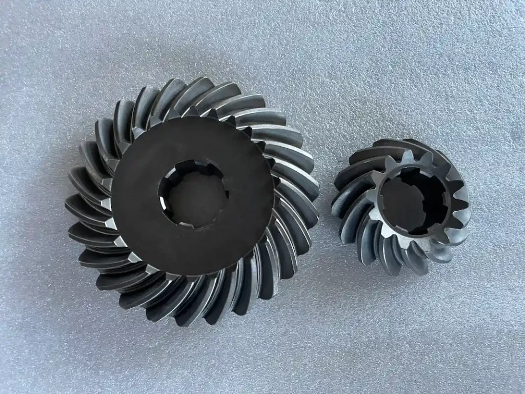
The shafts connected by bevel gears may intersect, such as in a conventional 90-degree right-angle drive, or be offset from one another in designs such as hypoid gears.
How Do Bevel Gears Work?
A bevel gear pair transfers torque from the driving pinion to the mating gear through tooth engagement. The pitch cone defines the basic geometry of the gear, while the pitch cone angle determines its relationship with the mating gear. Because the teeth taper along the face width, the larger end is called the heel and the smaller end the toe.
Tooth contact produces tangential, radial, and axial forces, with the exact force pattern according to the gear design and operating load. Tooth shape matters too. Straight bevel gears engage more abruptly, while spiral bevel gears provide greater tooth overlap and smoother engagement. Hypoid gears add shaft offset, resulting in different contact and sliding characteristics. These differences form the basis for the main types of bevel gears.
How Are Bevel Gears Classified?
Bevel gears can be classified from two complementary perspectives: tooth geometry and shaft arrangement.
1.Classification by tooth geometry
The shape and orientation of the teeth along the face of a bevel gear strongly affect tooth engagement, contact characteristics, load distribution, noise, and operating speed. Based on tooth geometry, common designs include:
- Straight bevel gears: The teeth run essentially straight from the heel toward the toe.
- Spiral bevel gears: The teeth follow a curved, spiral path, creating greater overlap between mating teeth.
- Zerol bevel gears: The teeth are curved in the lengthwise direction while having a mean spiral angle close to zero.
- Skew-tooth bevel gears: The tooth geometry is arranged to accommodate specialized transmission requirements and differs from conventional intersecting-axis bevel gear designs.
These differences in tooth form are not merely cosmetic. They determine how quickly teeth enter and leave mesh, how loads are shared between teeth, and how the gear behaves at different speeds and loads.
2. Classification by shaft arrangement
The relationship between the two shaft axes provides another important way to distinguish bevel-type gears:
- Intersecting-shaft bevel gears: The two shaft axes intersect, as is common with straight, spiral, and Zerol bevel gears.
- Offset-shaft designs: The shaft axes do not intersect and are separated by a defined offset. Hypoid gears are the most important example of this configuration.
Shaft arrangement directly affects the transmission layout, gear geometry, bearing loads, lubrication requirements, and available reduction ratio. For example, a conventional spiral bevel gear pair can provide a compact right-angle transmission with intersecting shafts, whereas a hypoid arrangement uses shaft offset to provide additional packaging and gearing possibilities.
Therefore, when comparing the types of bevel gears, it is important to consider both the shape of the teeth and the relationship between the shafts.
What Are the Main Types of Bevel Gears?
Bevel gears can be distinguished by their tooth form, spiral angle, and shaft arrangement.
| Bevel Gear Type | Image | Tooth Design | Shaft Arrangement | Main Characteristics | Typical Applications |
| Straight Bevel Gear | 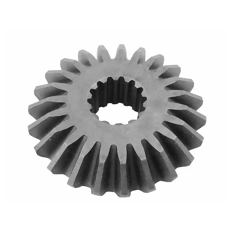 |
Straight teeth tapering toward the toe | Intersecting | Simple geometry, direct tooth engagement, economical for moderate-speed service | Low-speed drives, agricultural machinery, general machinery |
| Spiral Bevel Gear | 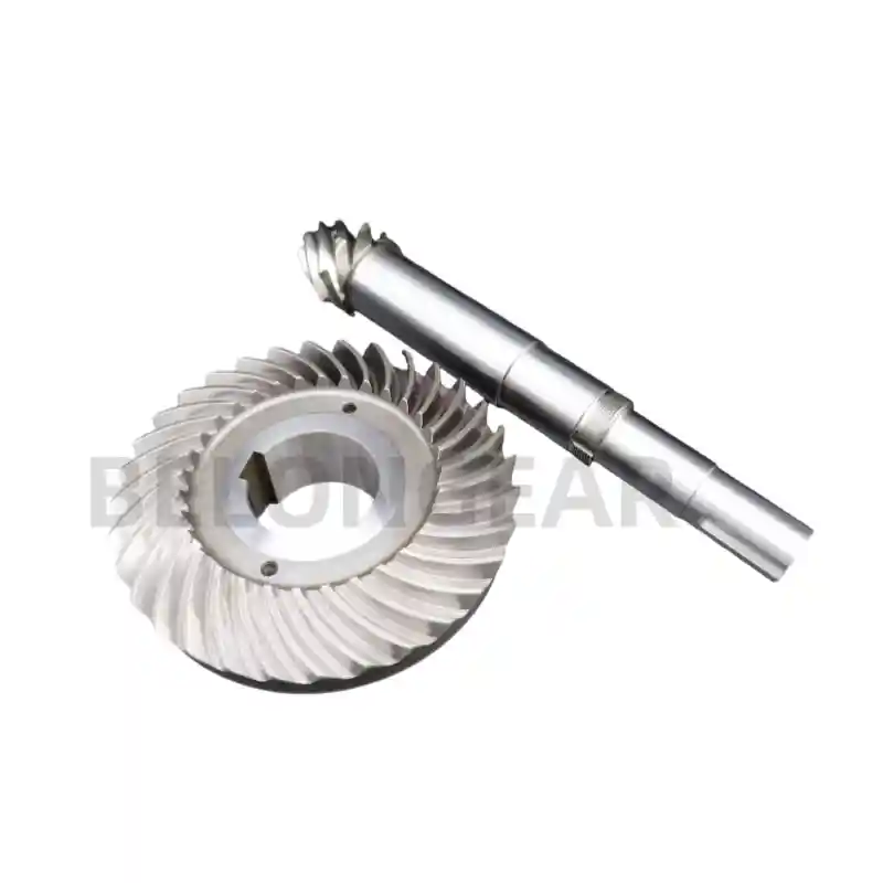 |
Curved, spiral teeth | Intersecting | Greater tooth overlap, smoother engagement, suitable for higher speeds and loads | Industrial gearboxes, automotive drives, marine transmissions |
| Zerol Bevel Gear | 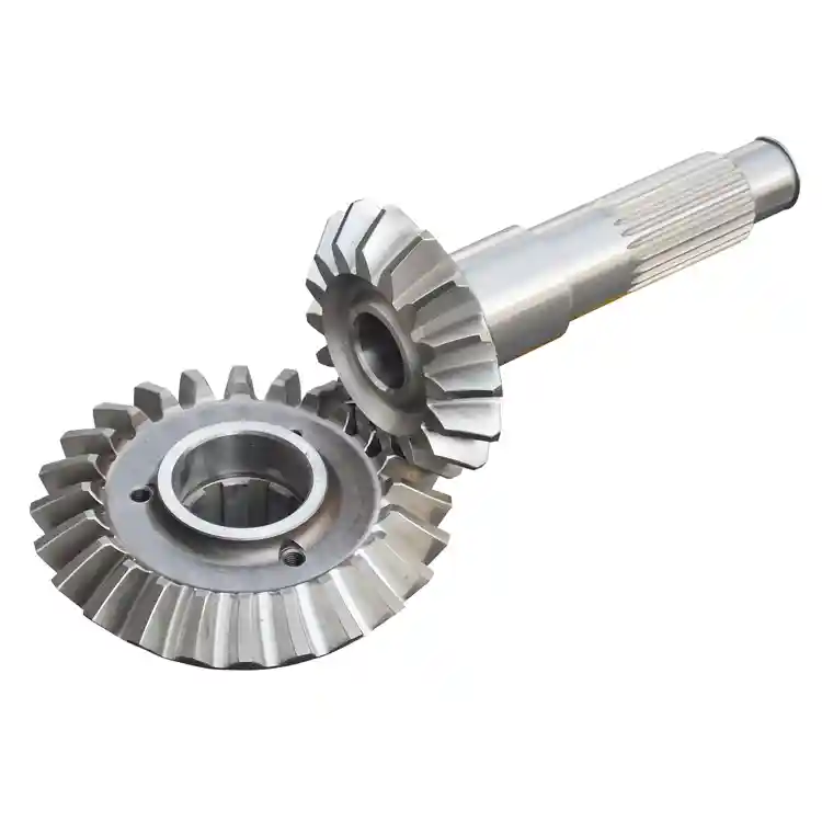 |
Curved teeth with a mean spiral angle close to zero | Intersecting | Combines curved-tooth contact characteristics with thrust behavior closer to straight bevel gears | High-speed machinery, specialized right-angle drives |
| Hypoid Gear |  |
Curved teeth with an offset between the pinion and gear axes | Non-intersecting | Offset shaft arrangement, high reduction potential, substantial sliding contact | Automotive differentials, vehicle axles, compact drivetrains |
| Miter Gear |  |
Usually straight or spiral bevel teeth with a 1:1 ratio | Intersecting | Changes the direction of rotation without intentionally changing speed or torque ratio | Right-angle drives, machine tools, automation equipment |
Among these designs, straight, spiral, and Zerol bevel gears are primarily differentiated by tooth geometry, while hypoid gears are distinguished by their offset shaft arrangement and resulting tooth contact. Miter gears are different again: the term generally describes a 1:1 bevel gear arrangement rather than a separate tooth form.
The following sections examine each type in more detail, including its geometry, operating characteristics, advantages, limitations, and common applications.
Straight Bevel Gears
A straight bevel gear has straight teeth arranged on a conical pitch surface. In a conventional straight bevel gear pair, the two shaft axes intersect, often at 90°. When two straight bevel gears mesh, contact develops across the tooth face rather than gradually building through a long curved path.

Advantages of Straight Bevel Gears
- Simple tooth geometry: comparatively uncomplicated form, making the straight bevel gear easier to design and manufacture.
- Lower manufacturing complexity: generally require less complex tooth-generation processes.
- Cost-effective: economical for applications with moderate performance requirements.
- Direct power transmission: The intersecting shaft arrangement provides a simple way to transfer torque and change the direction of rotation.
- Suitable for moderate operating conditions: perform effectively where operating speed, noise, and dynamic loading are not particularly demanding.
Limitations of Straight Bevel Gears
The main limitation comes from the way their teeth enter and leave mesh. Straight teeth provide less overlap and a more abrupt engagement.
This can lead to:
- More pronounced impact during tooth engagement
- Higher noise and vibration at increasing speeds
- Greater sensitivity to tooth contact and mounting accuracy
- Less favorable operating characteristics for high-speed applications
Applications of Straight Bevel Gears
Straight bevel gears are commonly used where a simple right-angle transmission is required without the additional manufacturing complexity of spiral or hypoid designs. Typical applications include:
- Agricultural machinery: Drives and implements that require straightforward angular power transmission.
- Low-speed gearboxes: Machinery operating at moderate rotational speeds and loads.
- Hand tools: Compact mechanical drives where simplicity and cost are important.
- Light industrial machinery: Equipment with relatively moderate torque and speed requirements.
- Right-angle drives: Mechanical systems that need to redirect rotary motion between intersecting shafts.

Straight bevel gear used for agricultural machinery
For applications requiring higher speed, smoother tooth engagement, greater load capacity, or lower operating noise, spiral bevel gears may provide a more suitable alternative instead of straight bevels. [Request A Quote For Straight Bevel Gears]
Spiral Bevel Gears
A spiral bevel gear has curved teeth that follow a spiral path across the face of the gear. Unlike the straight teeth of a conventional bevel gear, the curved tooth form enables the mating teeth to enter and leave contact progressively. The result is greater tooth overlap and a more continuous transfer of load during meshing.
The spiral angle describes the inclination of the tooth relative to the gear geometry and is an important parameter in spiral bevel gear design. In a conventional spiral bevel gear pair, the two shaft axes intersect, commonly at 90°.
Because several portions of the tooth can participate in the mesh as the gears rotate, spiral bevel gears generally provide smoother operation than straight bevel gears.

Tractor spiral bevel gears
Advantages of Spiral Bevel Gears
- Smoother tooth engagement: The curved teeth enter and leave mesh progressively.
- Lower operating noise: Greater tooth overlap reduces sudden changes in tooth loading, which can help reduce noise and vibration.
- Higher load-carrying capability: The increased overlap and favorable contact conditions allow spiral bevel gears to handle demanding loads when properly designed.
- Better high-speed performance: More progressive engagement makes spiral bevel gears well suited to higher rotational speeds.
- Improved contact characteristics: Curved teeth provide a larger and more controlled area of contact, helping distribute the transmitted load across the mating teeth.
- Suitable for demanding power transmission: Their combination of load capacity, speed capability, and smooth operation makes them a common choice for industrial and mobile power transmission systems.
Limitations of Spiral Bevel Gears
The performance advantages of spiral teeth come with greater design and manufacturing requirements.
- More complex manufacturing: Generating the curved tooth geometry requires more sophisticated gear-cutting and finishing processes than straight bevel gears.
- Higher manufacturing cost: Additional machining complexity, tooling requirements, and inspection can increase production cost.
- Axial thrust: The spiral tooth orientation generates axial force in addition to tangential and radial forces. Bearings and shafts therefore need to be designed to accommodate the resulting thrust loads.
- Greater alignment sensitivity: Accurate mounting, shaft positioning, and gear adjustment are important for achieving the intended tooth contact pattern.
- More demanding inspection: Because tooth geometry and contact conditions are more complex, precision measurement and meshing inspection become increasingly important for high-performance applications.
Applications of Spiral Bevel Gears
Spiral bevel gears are widely used when a transmission requires a combination of high load capacity, smooth operation, and relatively high rotational speed. Typical applications include:
- Industrial gearboxes: Used in right-angle transmission stages where continuous power transmission and low vibration are important.
- Mining equipment: Suitable for demanding drives exposed to high torque and heavy operating loads.
- Construction machinery: Used in drivetrains and transmission systems where compact angular power transfer is required.
- Marine transmissions: Applied in propulsion and auxiliary drives where smooth and reliable torque transmission is important.
- Automotive systems: Used in driveline and differential applications requiring efficient transfer of power between intersecting shafts.
- High-speed machinery: Suitable for applications where straight bevel gears may produce excessive dynamic impact, noise, or vibration.

Spiral bevel gear set used in automotive gearboxes
Spiral bevel gears offer a more gradual meshing action and better performance under demanding operating conditions, but their more complex geometry makes manufacturing, inspection, and installation more demanding. [Request A Quote For Spiral Bevel Gears]
Zerol Bevel Gears
A Zerol bevel gear has curved teeth, but its spiral angle is approximately zero. In this respect, it differs from a conventional spiral bevel gear, where the teeth have a definite spiral angle. Like straight and spiral bevel gears, Zerol gears normally operate on intersecting shaft axes.
The curved tooth form gives Zerol gears more favorable contact characteristics than straight bevel gears, while the near-zero mean spiral angle keeps their thrust behavior closer to that of straight bevel gears.
How Is a Zerol Bevel Gear Different from a Straight Bevel Gear?
The main difference is the shape of the tooth along the face of the gear. Straight bevel gears have essentially straight teeth, whereas Zerol gears use curved teeth with a mean spiral angle close to zero.
This change in tooth geometry affects the way the gears mesh. Zerol teeth offer more favorable and localized contact than straight teeth, reducing the abruptness of engagement. At the same time, because the mean spiral angle is near zero, the resulting thrust characteristics remain relatively similar to those of straight bevel gears.
Manufacturing is also different. Straight bevel gears can be produced with comparatively simple cutting arrangements, while Zerol gears require equipment and tooling capable of generating their curved tooth geometry. Based on the design and production method, Zerol gears can also be finished by grinding to achieve the required tooth accuracy and surface quality.
Advantages and Limitations of Zerol Bevel Gears
Zerol bevel gears offer a useful combination of curved-tooth contact and near-zero mean spiral angle.
Advantages include:
- Smoother engagement than straight bevel gears: The curved tooth form means a more favorable transition into mesh.
- Improved contact conditions: The tooth geometry has a more localized and controlled contact pattern.
- Lower thrust tendency than conventional spiral bevel gears: With a spiral angle close to zero, the thrust characteristics are closer to those of straight bevel gears.
- Suitable for precision finishing: Zerol gears can be manufactured and, where required, ground to achieve higher tooth accuracy.
- Compact right-angle transmission: Like other intersecting-axis bevel gears, they can transmit power through a compact angular arrangement.
There are also some limitations. The curved tooth geometry requires more specialized manufacturing than a conventional straight bevel gear, which can correspondingly increase tooling, machining, and inspection requirements for manufacturers. Zerol gears are not automatically the best choice for every high-speed application; operating speed, load, tooth size, lubrication, and required accuracy still need to be considered during design.
Applications of Zerol Bevel Gears
Zerol bevel gears are useful in applications that need smoother operation than straight bevel gears while keeping axial thrust relatively controlled.
Typical applications can include:
- High-speed accessory drives
- Turbine and aerospace equipment
- Helicopter transmission systems
- Specialized industrial gearboxes
- Precision right-angle drives
- Machinery where controlled thrust loads are important
The choice between Zerol and spiral bevel gears ultimately relies on the required combination of speed, load, tooth contact, axial thrust, accuracy, and manufacturing capability. [Request A Quote For Zerol Gears]
Hypoid Bevel Gears
A hypoid gear is a bevel-type gear set with curved teeth whose two shaft axes do not intersect. Instead, the pinion and gear are separated by a defined shaft offset. This is the main geometric feature that distinguishes a hypoid gear from conventional intersecting-axis bevel gears.
The tooth surfaces are generated from a geometry related to a hyperboloid of revolution, rather than the simple conical arrangement used for conventional bevel gears. The offset also changes the way the teeth contact each other. Instead of primarily rolling across the tooth surfaces, hypoid gears experience a significant amount of sliding contact during operation.
This geometry allows the pinion and gear to be positioned in a compact arrangement while providing gearing characteristics that are difficult to achieve with a conventional bevel gear pair.
How Does a Hypoid Gear Work?
Power enters the system through the hypoid pinion. As the pinion rotates, its curved teeth engage the mating gear and transmit torque across the offset shaft arrangement.
The key difference is the relative position of the two axes. Because they do not intersect, the pinion can be positioned below, above, or otherwise offset from the gear centerline depending on the design.
During meshing, the teeth experience both rolling and considerable sliding motion. The sliding action contributes to friction and heat generation, so lubrication is particularly important in hypoid transmissions. Under load, the initial tooth contact develops into a broader contact region, making the transmitted force distributed over the working portion of the tooth surface.
The combination of shaft offset, curved teeth, and sliding contact is what gives hypoid gears their distinctive operating characteristics.
Advantages of Hypoid Gears
Hypoid geometry provides several benefits for applications where space, torque, and gear ratio are important.
- High load-carrying capability: The tooth geometry and relatively large contact area can support substantial loads when the gear set is properly designed.
- Compact packaging: Shaft offset provides greater freedom when positioning the input and output shafts, which is particularly useful where available space is limited.
- Higher reduction ratios: A hypoid pinion can use a relatively small number of teeth, allowing higher gear ratios within a compact gear set.
- Larger pinion diameter: Compared with a conventional bevel arrangement at a similar ratio, the hypoid design can accommodate a larger and stronger pinion geometry.
- Smooth operation: Curved teeth and progressive engagement help provide smoother transmission than straight bevel gears.
- Lower operating noise: The gradual tooth engagement and favorable contact characteristics can reduce noise and vibration, particularly when the gear set is accurately manufactured and properly adjusted.
Limitations of Hypoid Gears
The same geometry that gives hypoid gears their advantages also introduces additional design requirements.
- Greater sliding: Sliding velocity is higher than in conventional bevel gear contact.
- Higher friction and heat generation: Increased sliding produces additional frictional losses, making thermal management and lubrication more important.
- Specialized lubrication: Hypoid gear sets generally require lubricants capable of handling high contact pressure and sliding conditions.
- More complex manufacturing: Generating the offset tooth geometry requires specialized gear-cutting and finishing processes.
- Higher manufacturing cost: More complex geometry, tooling, machining, and inspection can increase production cost compared with simpler bevel gear designs.
- Greater sensitivity to adjustment: Correct mounting distance, alignment, backlash, and tooth contact are important for maintaining the intended contact pattern and service life.
Applications of Hypoid Gears
Hypoid gears are particularly useful where high torque, compact packaging, shaft offset, and substantial reduction ratios are required.
- Automotive differentials: the offset arrangement allows the drivetrain to be packaged efficiently while transmitting high torque.
- Rear axles: Common in vehicle final-drive systems, where the hypoid arrangement can lower the driveshaft position relative to the axle centerline.
- Electric vehicles: Used in compact reduction and final-drive systems where packaging, torque density, and low noise are important.
- Heavy-duty vehicle drivetrains: Suitable for applications requiring high torque transmission and robust gear performance.
- Compact transmission systems: Useful when the input and output shafts need to remain non-intersecting while fitting within a constrained installation space.
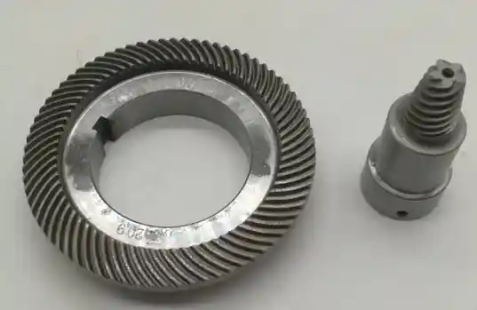
Hypoid bevel gears used in mountain bikes
Compared with conventional spiral bevel gears, hypoid gears provide greater freedom in shaft positioning and can achieve high reduction ratios, but the additional sliding makes lubrication, heat control, and gear adjustment more critical. [Request A Quote For Hypoid Gears]
Miter Gears
A miter gear is a bevel gear pair designed primarily to change the direction of rotation while maintaining a 1:1 gear ratio. The two gears normally have the same number of teeth and are mounted on intersecting shafts, commonly at 90°.
Miter gear describes the arrangement and ratio of the gear pair rather than a separate tooth geometry. This characteristic is quite different from straight, spiral and hypoid bevel gears. Miter gears can use straight or spiral bevel teeth depending on the required operating conditions.
Because the gear ratio is 1:1, the input and output shafts rotate at essentially the same speed, while the torque ratio is also approximately 1:1 before considering losses.
How Do Miter Gears Work?
A miter gear set transfers rotational motion from one shaft to another through a pair of bevel gears whose axes intersect. The driving gear rotates the mating gear, redirecting the power flow—typically through 90 degrees.
Both gears normally have the same pitch diameter and tooth count. As a result, the gear pair does not provide intentional speed reduction or speed increase.
For example, a 20-tooth driving gear meshing with another 20-tooth gear produces a 1:1 transmission ratio. The output shaft therefore rotates at approximately the same speed as the input shaft, but along a different axis.
The actual torque and power delivered at the output are affected by gear efficiency, friction, and operating conditions. Miter gears are therefore primarily selected for direction change rather than mechanical advantage.
Miter Gears vs. Bevel Gears
Miter gears are technically a specific application of bevel gears, so the distinction is mainly related to gear ratio and purpose.
| Feature | Miter Gears | General Bevel Gears |
| Gear ratio | Normally 1:1 | Can provide reduction or speed increase |
| Tooth count | Usually equal on both gears | May be different |
| Shaft arrangement | Intersecting, commonly 90° | Intersecting or offset depending on design |
| Primary purpose | Change direction of rotation | Change direction and/or speed |
| Input/output speed | Approximately the same | Can be different |
| Torque relationship | Approximately 1:1 before losses | Depends on gear ratio |
| Typical use | Direction-changing drives | Power transmission and speed reduction |
The tooth form can also differ. A miter gear pair may use straight bevel teeth for simpler, lower-speed applications or spiral bevel teeth when smoother operation and higher-speed performance are required.
Applications of Miter Gears
Miter gears are useful where machinery needs to redirect rotary motion without intentionally changing the transmission ratio. Common applications include:
- Right-angle drives: Redirecting power through 90° in compact mechanical systems.
- Machine tools: Transmitting rotary motion between intersecting shafts within machine mechanisms.
- Conveyors: Changing the direction of a drive while maintaining approximately the same rotational speed.
- Automation equipment: Connecting drive components positioned at right angles.
- Mechanical instruments: Providing compact angular motion transmission in precision mechanisms.
- General machinery: Used wherever a simple 1:1 direction-changing drive is required.
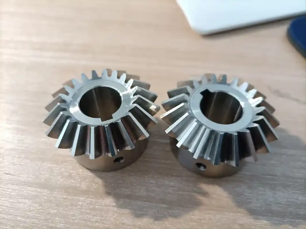
Industrial miter bevel gears
For applications that require speed reduction, higher torque multiplication, or non-intersecting shafts, engineers should note that a conventional bevel gear pair or a hypoid gear set may be more appropriate than a miter gear arrangement. [Request A Quote For Miter Gears]
Straight vs. Spiral vs. Zerol vs. Hypoid Bevel Gears
Straight, spiral, Zerol, and hypoid gears all transmit power between angularly arranged shafts, but their geometry and operating behavior are quite different. The table below summarizes the key differences.
| Feature | Straight Bevel | Spiral Bevel | Zerol Bevel | Hypoid |
| Tooth shape | Straight | Curved / spiral | Curved | Curved / spiral |
| Spiral angle | 0° | Typically non-zero | ≈ 0° | Non-zero / geometry-dependent |
| Shaft axes | Intersecting | Intersecting | Intersecting | Non-intersecting |
| Shaft offset | 0 | 0 | 0 | > 0 |
| Tooth engagement | Relatively abrupt | Progressive | More progressive than straight | Progressive with sliding |
| Tooth overlap | Lower | Higher | Higher than straight | High |
| Sliding contact | Relatively limited | Present | Present but controlled by geometry | Significant |
| Noise / vibration | Relatively higher | Lower | Lower than straight | Generally low |
| High-speed suitability | Lower | High | Moderate to high, application-dependent | High |
| Load capability | Moderate | High | Moderate to high | High |
| Axial / thrust load | Characteristic | Higher tendency | Closer to straight bevel | Significant / design-dependent |
| Manufacturing complexity | Low | High | High | Very high |
| Manufacturing cost | Lower | Higher | Higher | Higher |
| Typical transmission | Right-angle | Right-angle | Right-angle | Offset-axis |
| Typical application | Low-speed machinery | High-speed/high-load drives | Specialized high-speed drives | Automotive/heavy-duty drives |
What Do These Differences Mean in Practice?
- Straight bevel gears have the simplest tooth geometry. Their relatively abrupt engagement makes them a practical choice for moderate-speed applications where manufacturing simplicity and cost are important.
- Spiral bevel gears use curved teeth and greater tooth overlap. The progressive engagement improves the operating characteristics of the gear set, making them better suited to higher speeds and heavier loads, although they also generate greater thrust and require more sophisticated manufacturing.
- Zerol bevel gears occupy a distinctive position. Their teeth are curved, but the mean spiral angle is approximately zero. They therefore offer improved tooth contact compared with straight bevel gears while retaining thrust characteristics closer to a straight bevel design.
- Hypoid gears differ most significantly in shaft geometry. The axes do not intersect, and the offset creates substantial sliding between the tooth surfaces. This allows compact packaging and high reduction ratios, but places greater demands on lubrication, heat control, and tooth-contact adjustment.
How to Choose the Right Type of Bevel Gear?
Choosing the right bevel gear is not simply a matter of selecting straight, spiral, Zerol, or hypoid teeth. The gear must match the shaft arrangement, speed, torque, loading pattern, noise requirements, lubrication system, and manufacturing accuracy of the transmission.
Consider Shaft Arrangement
Start with the relationship between the two shafts.
- Do the shaft axes intersect?
If the two shafts intersect, a conventional bevel gear design such as a straight, spiral, or Zerol bevel gear may be suitable. - Is shaft offset required?
If the axes must remain non-intersecting, a hypoid gear is a more appropriate option. The offset can provide additional freedom for drivetrain packaging and gear ratio design. - Is a 90-degree transmission needed?
A 90° shaft arrangement is common in bevel gear applications, but it does not by itself determine the tooth type. Both straight and spiral bevel gears, for example, can be designed for right-angle transmission.
For a 1:1 right-angle drive, a miter gear arrangement may be sufficient when the primary purpose is to change the direction of rotation rather than increase torque or reduce speed.
Consider Speed and Operating Conditions
Operating speed is one of the main factors affecting bevel gear selection.
For relatively low-speed machinery, straight bevel gears can provide a practical and economical solution. As rotational speed increases, abrupt tooth engagement becomes more important, making the progressive engagement of spiral bevel gears increasingly attractive as a better choice.
The design should consider more than rotational speed alone:
- Rotational speed: Input and output rpm affect tooth engagement and dynamic loading.
- Pitch line velocity: Tooth surface speed provides a better indication of the operating severity than rpm alone.
- Duty cycle: Continuous operation places different demands on the gear than intermittent service.
- Operating time: Long operating periods increase the importance of heat generation, lubrication, and fatigue life.
- Starting and stopping conditions: Frequent acceleration, deceleration, or reversing can increase dynamic loads.
- Temperature: Ambient and operating temperatures influence lubricant performance and gear durability.
A gear operating at high rpm but with a very small diameter may have a different pitch line velocity from a much larger gear running at the same speed. Both speed and gear dimensions therefore need to be considered together.
Consider Load and Torque
The gear must be capable of transmitting the required torque without exceeding the allowable tooth and shaft stresses.
Key load conditions include:
- Transmitted torque: Determines the basic tooth loading and required gear size.
- Radial load: Acts perpendicular to the shaft and affects bearing selection and shaft design.
- Axial load: Particularly important for spiral and hypoid gears because their tooth geometry can generate significant thrust.
- Shock load: Sudden impacts, starts, stops, and load changes can substantially increase the effective tooth load.
- Service factor: Accounts for variations between the nominal operating load and the actual duty conditions.
For demanding industrial applications, gear selection should therefore consider the maximum operating torque, not only the average torque.
A spiral or hypoid gear may offer advantages under high-load conditions, but the final load capacity still need to consider factors such as module, face width, tooth geometry, material, heat treatment, accuracy, lubrication, and operating speed.
Consider Noise and Vibration Requirements
Noise and vibration become increasingly important as gear speed rises.
- Straight bevel gears have relatively abrupt tooth engagement, which can produce greater dynamic impact and noise compared with curved-tooth designs. They may still be perfectly adequate for low-speed machinery where acoustic performance is not critical.
- Spiral bevel gears provide more progressive tooth engagement and greater overlap, making them a better choice when smooth operation and reduced vibration are important.
- Hypoid gears can also provide smooth operation, but their significant sliding contact introduces additional friction and heat that must be considered alongside the noise requirement.
For noise-sensitive applications, tooth geometry should therefore be evaluated together with gear accuracy, surface finish, contact pattern, backlash, mounting accuracy, and operating speed.
Consider Lubrication Requirements
Lubrication matters when the gear operates under high load, high speed, or significant sliding conditions.
For conventional bevel gears, the lubricant must maintain an adequate film between the mating tooth surfaces and help remove heat from the contact zone.
Hypoid gears require particular attention because their offset geometry produces substantial sliding contact. This increases friction and heat generation and places greater demands on the lubricant.
Important lubrication factors include:
- Lubricant type: The lubricant must be compatible with the gear material, operating conditions, and contact stresses.
- EP (extreme-pressure) performance: Hypoid applications commonly require lubricants with suitable extreme-pressure characteristics.
- Oil viscosity: Viscosity must match the operating speed, load, and temperature range.
- Operating temperature: Excessive temperature can reduce lubricant viscosity and accelerate degradation.
- Lubricant supply: Splash, bath, or forced lubrication may be considered depending on gear speed and transmission design.
Lubrication should be selected as part of the gear system, rather than as an isolated gear specification.
Consider Manufacturing Cost and Accuracy
The most sophisticated gear design is not necessarily the best choice if its performance is unnecessary for the application.
Straight bevel gears generally have simpler tooth geometry and can be more economical to manufacture. Spiral, Zerol, and hypoid gears require more specialized manufacturing and inspection, particularly when high accuracy and demanding contact patterns are required.
The manufacturing route may include:
Gear cutting → heat treatment → hard finishing → grinding/lapping → dimensional inspection → tooth contact inspection
The required manufacturing accuracy should match the operating conditions. High-speed and low-noise transmissions demand tighter control of tooth geometry, runout, backlash, surface finish, and contact pattern.
Grinding can improve tooth accuracy and surface finish after heat treatment, while lapping can be used on suitable bevel gear sets to improve tooth contact and running characteristics. Inspection may include dimensional measurement, hardness testing, and dedicated gear measurement or meshing tests.
Bevel Gear Types by Application
Different industries place different demands on bevel gears. Speed, torque, shock loading, noise, available installation space, and shaft arrangement can all influence the appropriate gear design. The following examples show how common bevel gear types are used in different applications.
Bevel Gears for Industrial Gearboxes
Industrial gearboxes often require reliable power transmission under continuous loads, high torque, and varying operating speeds. Spiral bevel gears are commonly used when smooth meshing, higher load capacity, and reduced vibration are important, particularly in right-angle gearbox stages. Straight bevel gears may be suitable for simpler, lower-speed transmissions, while Zerol bevel gears can be considered for specialized applications where curved tooth contact and controlled thrust characteristics are required. Typical equipment includes industrial reducers, conveyor drives, pumps, compressors, and machine tools.

Spiral bevel gears used for gearboxes
Bevel Gears for Automotive Differentials
Hypoid gears are widely associated with automotive differential and final-drive systems because their offset shaft arrangement allows the driveshaft and differential to be positioned efficiently within the vehicle. The curved teeth provide progressive engagement, while the offset geometry can accommodate high reduction ratios and substantial torque transmission in a relatively compact package. Hypoid gears are also increasingly relevant to electric vehicle reduction systems, where compact packaging, torque density, efficiency, and noise control are important design considerations.

Hypoid bevel gears for speed reducer
Bevel Gears for Mining and Construction Equipment
Mining and construction machinery subjects gears to high torque, shock loads, heavy duty cycles, and contaminated operating environments. Spiral bevel gears are often preferred for demanding right-angle drives because their curved tooth geometry provides smoother engagement and good load-carrying capability. Hypoid designs may also be considered where shaft offset and compact packaging are beneficial. Typical applications include mining conveyors, crushers, excavators, loaders, drilling equipment, and heavy-duty transmission systems.
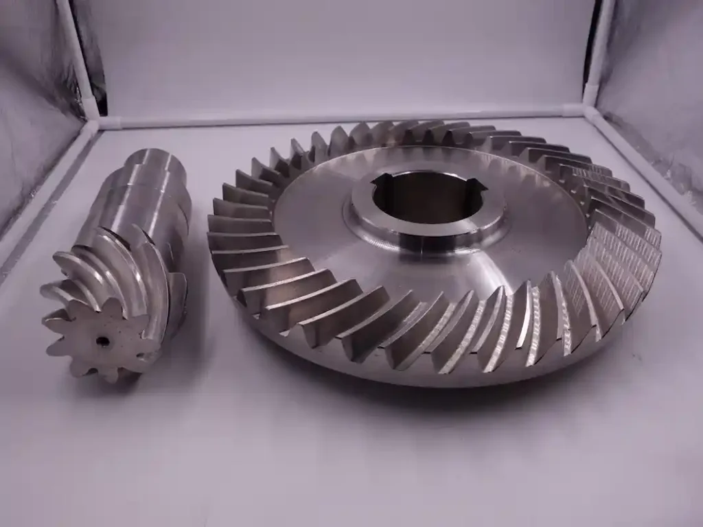
Ground bevel gear used for concrete mixer
Bevel Gears for Agricultural Machinery
Agricultural equipment commonly uses bevel gears to redirect power between shafts in tractors, harvesters, rotary tillers, balers, irrigation equipment, and other farm machinery. Straight bevel gears can provide a cost-effective solution for relatively simple and moderate-speed drives, while spiral bevel gears are better suited to applications requiring smoother operation and greater load capacity. Gear selection also needs to account for shock loads, intermittent operation, dust, moisture, and frequent changes in operating conditions.

Bevel gear used in agricultural gearbox
Bevel Gears for Marine Applications
Marine transmissions require gears capable of operating reliably under high torque, continuous duty, and demanding lubrication and environmental conditions. Spiral bevel gears are suitable for angular power transmission where smooth engagement and controlled vibration are important. They can be found in marine reduction gearboxes, propulsion systems, auxiliary drives, and other onboard machinery. Material selection, heat treatment, corrosion resistance, lubrication, and tooth accuracy become particularly important when the gear set is exposed to long operating cycles and high loads.

Straight bevel gear shaft for boat
Bevel Gears for Robotics and Automation
Robotics and automation systems typically place greater emphasis on precision, backlash, repeatability, compactness, and low noise than conventional heavy-duty machinery. Precision spiral bevel gears can be used to transfer motion between intersecting shafts while maintaining controlled tooth contact and smooth operation. Smaller bevel gear sets may also be incorporated into robotic joints, articulated mechanisms, positioning systems, servo-driven equipment, and automated machinery where space is limited and accurate angular motion is required.
Bevel Gear Manufacturing and Precision Requirements
The performance of a bevel gear depends not only on its tooth design but also on how accurately the gear is manufactured, heat-treated, finished, and inspected. For custom bevel gears and precision transmission components, each stage can affect tooth contact, load capacity, noise, and service life.
Bevel Gear Cutting
Bevel gear cutting forms the basic tooth geometry required for the selected gear type. Depending on the design, manufacturers may use specialized processes to produce straight, spiral, Zerol, or hypoid tooth forms. Tooth geometry, pitch, pressure angle, spiral angle, and other dimensions need to be controlled during machining.
Heat Treatment
Heat treatment improves the mechanical properties required for loaded gear applications. Processes such as carburizing, quenching, tempering, or induction hardening can be selected according to the gear material and service requirements. The goal is typically to obtain a hard, wear-resistant tooth surface while maintaining a tougher core.
Gear Grinding and Lapping
After heat treatment, precision bevel gears may require additional finishing. Gear grinding improves tooth accuracy and surface finish, while gear lapping can improve the mating tooth contact and running characteristics of suitable bevel gear pairs.
Bevel Gear Meshing Inspection
Meshing inspection evaluates how the pinion and gear actually contact under controlled conditions. The resulting contact pattern, backlash, and tooth engagement provide important information about gear adjustment and manufacturing quality. This is particularly important for precision bevel gear sets where correct contact is essential to load distribution and service life.
Gear Accuracy and Quality Control
Precision bevel gear manufacturing requires dimensional and geometric inspection throughout production. Depending on the application, quality control may include CMM measurement, gear geometry inspection, hardness testing, runout measurement, surface inspection, and final meshing tests.
For demanding OEM applications, the required accuracy should be defined according to the applicable ISO, DIN, or AGMA requirements. This allows the manufacturing process and inspection standards to be matched to the actual speed, load, noise, and service-life requirements of the gear system.
Custom Bevel Gear Manufacturing at BELON
At BELON, we manufacture custom bevel gears for OEM equipment, industrial transmissions, and replacement applications. Our capabilities cover different bevel gear geometries, materials, heat treatments, accuracy requirements, and production volumes. Whether you need a replacement for an existing bevel gear or a completely new OEM design, BELON can help evaluate the gear requirements and develop a manufacturing solution around your application.
You can send us:
- Gear drawings or CAD files
- Photos and dimensions
- An existing gear sample
- A worn or damaged gear
- Mating gear information
- Required material or heat treatment
- Torque, speed, gear ratio, and application details
Our engineering team can review the information and discuss the appropriate gear type, material, manufacturing process, accuracy, and inspection requirements with you.
Have a bevel gear you need to customize or reproduce? Send us your drawing or sample details through the inquiry form, and let’s discuss the right solution for your application.
[Request a Quote / Send Your Gear Drawing →]
FAQs About Bevel Gear Types
Q1: What are the four main types of bevel gears?
The four commonly discussed types are straight bevel gears, spiral bevel gears, Zerol bevel gears, and hypoid gears. Straight, spiral, and Zerol bevel gears use intersecting shaft axes, while hypoid gears use an offset between non-intersecting shafts. Miter gears are also commonly used in bevel gear systems, but they describe a 1:1 gear arrangement rather than a separate tooth geometry.
Q2: What is the difference between straight and spiral bevel gears?
The main difference between them is tooth geometry. Straight bevel gears have straight teeth and engage relatively abruptly. That’s why they are simpler and generally more economical. Spiral bevel gears have curved teeth that engage progressively, displaying smoother operation, greater tooth overlap, and better suitability for higher speeds and heavier loads. Spiral bevel gears, however, require more complex manufacturing and generate additional axial thrust.
Q3: What is the difference between spiral and hypoid gears?
Both of them use curved teeth, but their shaft arrangements are different. Spiral bevel gears have intersecting shaft axes often, while hypoid gears have non-intersecting axes with a defined shaft offset. Hypoid gears also have greater sliding contact, which can enable compact packaging and high reduction ratios but creates greater friction, heat, and lubrication requirements.
Q4: Which type of bevel gear is best for high-speed applications?
Spiral bevel gears are generally a preferred choice for high-speed applications because their curved teeth provide progressive engagement and greater tooth overlap, reducing dynamic impact, noise, and vibration compared with straight bevel gears. Zerol bevel gears can also be considered for certain specialized high-speed applications.
Q5: Which bevel gear is best for heavy-duty applications?
Spiral bevel and hypoid gears are commonly considered for heavy-duty applications because their tooth geometry can provide favorable load distribution and high load-carrying capability. Hypoid gears are particularly useful when high torque, shaft offset, compact packaging, or high reduction ratios are required.
Q6: How do I choose the right bevel gear type?
Start with the shaft arrangement. Use an intersecting-axis design such as straight, spiral, or Zerol bevel gears when the shafts intersect; consider hypoid gears when shaft offset is required. Then evaluate speed, torque, shock loading, noise, lubrication, accuracy, and cost. Straight bevel gears suit simpler moderate-speed drives, spiral bevel gears suit smoother high-speed transmission, and hypoid gears suit compact, high-torque offset applications.