

Abstract: Selecting the correct gear module is one of the most important decisions in gear design. As the primary parameter defining tooth size, the module directly affects gear strength, load capacity, center distance, and meshing compatibility. In this guide, you’ll learn what gear module is, how it differs from diametral pitch, how to calculate standard module sizes, and the key engineering factors to consider when selecting a module for different applications.
What Is Gear Module?
Definition of Gear Module
The gear module (m) is the fundamental parameter used in the metric gear system to define the size of a gear tooth. It represents the relationship between a gear’s pitch diameter and the number of teeth, serving as the basis for gear geometry, strength calculations, and manufacturing standards. In metric gear design, the module is the equivalent of the diametral pitch (DP) used in the imperial system.
The gear module is calculated using the following equation:
m=d/z
Where:
| Symbol | Description | Unit |
| m | Gear module | mm |
| d | Pitch diameter | mm |
| z | Number of teeth | — |
This formula shows that the module is the pitch diameter corresponding to one tooth. If the module increases, each tooth becomes larger and thicker, resulting in greater load-carrying capacity. Conversely, a smaller module produces finer teeth, allowing for more compact and lightweight gear designs.
Unlike arbitrary dimensions, gear modules follow standardized preferred values defined by international standards. Standard modules simplify gear manufacturing, ensure interchangeability, and allow gears produced by different manufacturers to mesh correctly when other key parameters—such as pressure angle and tooth profile—are also identical.
Why Gear Module Matters
Although the module is a single numerical value, it influences nearly every aspect of gear performance—from tooth geometry and strength to manufacturing processes and gear compatibility.
Determines Tooth Size
The module directly defines the dimensions of each gear tooth. A larger module results in thicker, deeper teeth with greater cross-sectional area, while a smaller module creates finer teeth suitable for compact mechanisms.
Determines Gear Strength
Because tooth thickness increases with module, the bending strength of each tooth also increases. Larger modules reduce bending stress at the tooth root and improve resistance to tooth breakage, suitable for applications involving heavy loads or shock loading.
However, selecting an excessively large module is not always beneficial. Oversized teeth increase gear weight, rotational inertia, manufacturing cost, and space requirements. Engineers therefore seek the smallest module that still satisfies strength and durability requirements. This design philosophy is widely adopted in modern gear engineering.
Determines Load Capacity
The module has a significant influence on the amount of torque a gear can safely transmit. As the module increases:
- Tooth thickness increases.
- The contact area between meshing teeth becomes larger.
- Load is distributed over a greater surface.
- Resistance to pitting and surface fatigue improves.
For this reason, high-torque applications such as industrial reducers, mining gearboxes, marine transmissions, and construction machinery typically employ larger modules than high-speed precision equipment.
Determines Gear Compatibility
Perhaps the most overlooked function of the module is ensuring proper meshing between gears.
Two gears cannot operate together unless they share the same module. Even if the gears have identical outside diameters or the same number of teeth, differences in module change the tooth spacing along the pitch circle, preventing correct engagement.
For two gears to mesh properly, they must typically have the same:
- Module
- Pressure angle
- Tooth profile
- Helix angle (for helical gears)
- Gear standard and manufacturing accuracy
This standardization allows replacement gears from different manufacturers to remain interchangeable when designed according to the same specifications.
Gear Module Formula and Calculation
Accurate gear calculations are essential for designing gears that mesh correctly and deliver the required strength and transmission performance. Since the module is the foundation of metric gear geometry, many other dimensions—including pitch diameter, outside diameter, center distance, and circular pitch—are derived directly from it.
Basic Formula
The module is calculated by dividing the pitch diameter by the number of teeth: m=d/z. This equation indicates that the module represents the pitch diameter allocated to each tooth. Once the module is known, nearly every other basic gear dimension can be calculated using standard formulas.
Example
Suppose a spur gear has:
- Number of teeth (z) = 40
- Pitch diameter (d) = 120mm
The module is: m=120/40=3
This means the gear belongs to the Module 3 (M3) standard series and should mesh only with another gear of the same module and compatible geometry.
Other Useful Gear Module Formulas
Once the module is determined, the remaining basic gear dimensions can be calculated using standard metric gear equations. These formulas are widely used for preliminary gear design and inspection.
| Parameter | Formula | Description |
| Module (m) | m = d / z | Basic tooth size |
| Pitch Diameter (d) | d = mz | Diameter of the pitch circle |
| Outside Diameter (da) | da = m(z + 2) | Outside diameter of a standard gear |
| Root Diameter (df) | df ≈ m(z − 2.5) | Approximate dedendum diameter for standard full-depth teeth* |
| Center Distance (a) | a = (d₁ + d₂) / 2 = m(z₁ + z₂) / 2 | Distance between two mating gear centers |
| Circular Pitch (p) | p = πm | Distance between adjacent teeth measured along the pitch circle |
Calculation Example
Example 1: Calculate the Module
A spur gear has:
- Number of teeth = 40
- Pitch diameter = 120 mm
Using the module equation: m=120/40=3
The gear is therefore a Module 3 gear. Using the calculated module, its basic dimensions can also be determined:
- Outside diameter = 3 × (40 + 2) = 126 mm
- Circular pitch = π × 3 ≈ 9.42 mm
Example 2: Calculate the Pitch Diameter
Now consider the reverse situation.
A gear is specified with:
- Module = 5
- Number of teeth = 32
Calculate the pitch diameter: d=m*z=2.5*32=80
Result: The pitch diameter is 80 mm.
Further dimensions can then be obtained:
- Outside diameter = 5 × (32 + 2) = 85 mm
- Circular pitch = π × 2.5 ≈ 7.85 mm
This reverse calculation is commonly used when designing a new gear from standard module specifications or verifying CAD models before manufacturing.
Standard Gear Module Sizes
To improve interchangeability and manufacturing efficiency, gear modules are standardized under ISO metric gear standards. Instead of using arbitrary values, engineers typically select from the preferred module series, ensuring compatibility with standard cutting tools, inspection equipment, and mating gears.
ISO Preferred Module Series
| Module (mm) | Typical Applications |
| 0.3–0.5 | Watches, instruments, medical devices |
| 0.6–1.0 | Robotics, automation, small gearboxes |
| 1.25–2.0 | Packaging machinery, conveyors, machine tools |
| 2.5–4.0 | Industrial gearboxes, reducers, agricultural equipment |
| 5.0–8.0 | Mining machinery, marine gearboxes, heavy equipment |
| 10–50 | Wind turbines, steel mills, large industrial transmissions |
Common ISO Preferred Module Numbers
| Standard Module Series (mm) |
| 0.3, 0.4, 0.5, 0.6, 0.8, 1, 1.25, 1.5, 2, 2.5, 3, 4, 5, 6, 8, 10, 12, 16, 20, 25, 32, 40, 50 |
Transverse Module vs Normal Module
For spur gears, there is only one module because the teeth are parallel to the gear axis. However, helical gears require two different module definitions due to the helix angle: transverse module and normal module. Understanding the difference is essential when designing or manufacturing helical gears.
Transverse Module and Normal Module Definition
- Transverse Module (mt): Measured in the gear’s transverse plane and used for gear geometry calculations.
- Normal Module (mn): Measured perpendicular to the tooth helix and commonly specified for helical gear manufacturing.
Transverse Module vs Normal Module
| Parameter | Transverse Module (mt) | Normal Module (mn) |
| Measurement Plane | Transverse (rotation) plane | Normal to the tooth helix |
| Used For | Gear geometry & pitch diameter | Gear cutting tools & manufacturing |
| Spur Gear | Same as normal module | Same as transverse module |
| Helical Gear | Larger than normal module | Standard value specified in design |
Conversion Formula
The relationship between the two modules is determined by the helix angle (β):
mt=mn/cosβ or mn=mt*cosβ
Where:
- mt= Transverse module
- mn= Normal module
- β= Helix angle
As the helix angle increases, the transverse module becomes larger than the normal module, while the normal module remains the reference value for manufacturing and inspection.
How to Choose the Right Gear Module
The module directly affects the gear tooth size, load-carrying capacity, center distance, gear strength, noise level, and overall transmission performance. However, gear module selection should not be based on module value alone. Engineers must consider torque, load conditions, operating speed, material properties, manufacturing method, and required accuracy.
Based on Torque
Higher torque transmission requires a larger module because:
- Larger modules create thicker tooth sections.
- Tooth bending strength increases with tooth size.
- The gear can withstand higher contact stress and shock loads.
For heavy-duty applications such as mining equipment, industrial gearboxes, marine propulsion systems and construction machinery, larger modules are commonly selected to ensure sufficient load capacity and service life.
For example, a small precision gearbox operating at low torque may use a fine module such as m0.5–m2, while heavy industrial transmission systems may require m5, m8, or larger modules.
Based on Load
Gear load conditions determine whether a standard module is sufficient or a reinforced design is required.
The main load factors include:
Continuous Load
For applications with stable operating conditions, such as factory automation equipment, conveyor systems, standard industrial gearboxes, a moderate module with optimized tooth width can provide sufficient performance.
Shock Load and Impact Load
Applications exposed to sudden torque changes require a larger module, such as crushers, agricultural machinery, mining equipment and heavy-duty reducers
Shock loads can cause:
- Tooth root bending failure
- Tooth chipping
- Surface pitting
Increasing module improves tooth thickness and bending resistance.
High Reliability Applications
For aerospace, marine, and critical industrial applications, module selection should include:
- Fatigue life calculation
- Contact stress analysis
- Heat treatment capability
- Gear accuracy requirements
BELON supports customized gear design by analyzing operating loads and selecting the appropriate module-tooth combination instead of simply matching standard dimensions.
Based on Speed
Gear speed also affects module selection.
High-Speed Applications
For high-speed gears:
- Smaller modules are often preferred.
- Fine pitch gears reduce sliding impact and noise.
- Precision manufacturing becomes more important.
Typical applications include:
- Robotics
- Servo systems
- Precision automation equipment
Low-Speed High-Torque Applications
For slow-speed transmissions, larger modules are usually preferred because strength and durability are more important than compact size.
Examples:
- Wind turbine gearboxes
- Mining reducers
- Marine drives
Based on Material
Gear material directly affects the required module because different materials have different strength limits.
Common gear materials include:
| Material | Characteristics | Typical Application |
| 20CrMnTi | Excellent wear resistance after carburizing, high contact fatigue strength | Automotive gears, industrial reducers |
| 18CrNiMo7-6 | High toughness and fatigue resistance for heavy loads | Mining and heavy-duty gearboxes |
| 8620 Steel | Good balance of strength and machinability | Industrial transmission systems |
| Stainless Steel | Corrosion resistance | Marine and food processing equipment |
| Brass / Bronze | Low friction and corrosion resistance | Worm gear systems |
Based on Manufacturing Process
The gear manufacturing process also influences the practical module selection. Different processes have different capabilities regarding gear size, accuracy, and surface quality.
Gear Hobbing
Hobbing is widely used for producing:
- Spur gears
- Helical gears
- Gear shafts
Advantages:
- High production efficiency
- Suitable for medium-volume manufacturing
- Wide module range capability
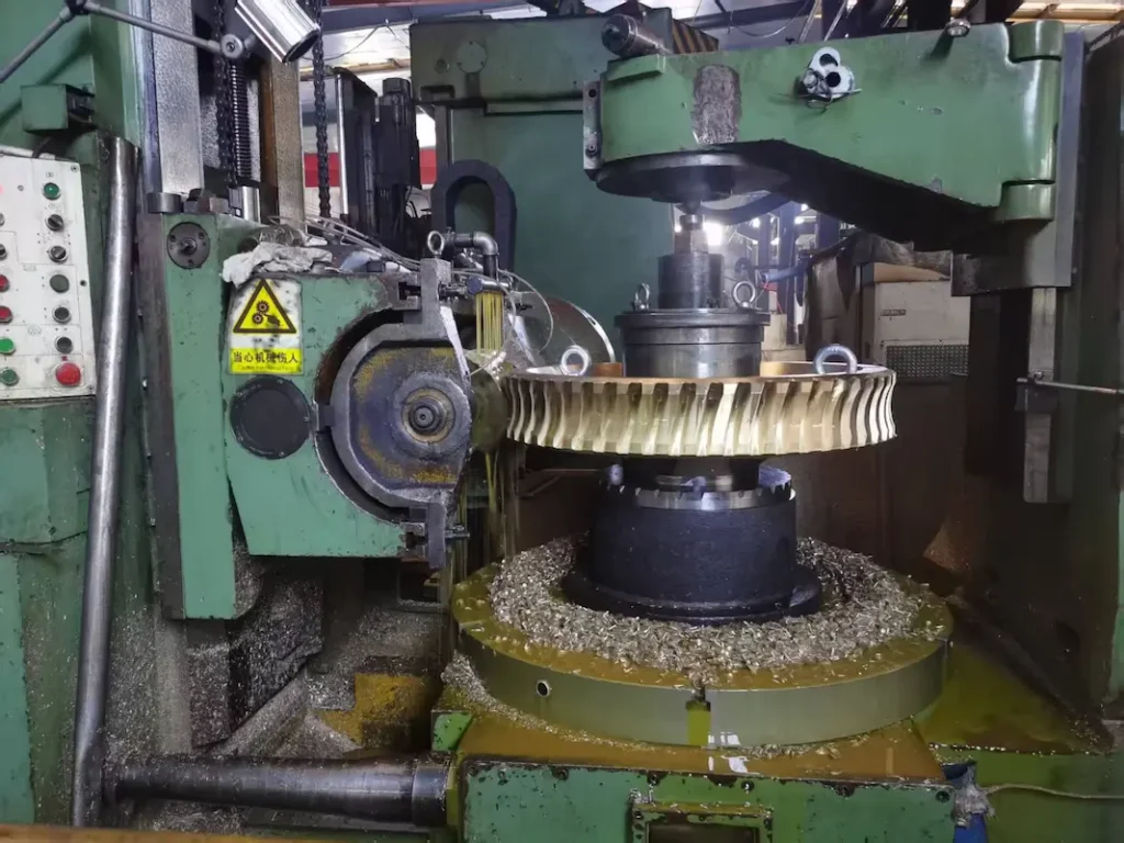
Worm gear hobbing process
Gear Shaping
Gear shaping is suitable for:
- Internal gears
- Shoulder gears
- Gears with limited machining access
Compared with hobbing, shaping provides greater flexibility for complex gear structures.
Gear Grinding
Grinding is used when high precision is required.
Advantages:
- Achieves higher gear accuracy grades
- Improves tooth surface finish
- Reduces transmission noise
Typical applications:
- Precision gearboxes
- Robotics
- Aerospace systems
- High-speed transmissions
For high-performance gears, a larger module does not automatically guarantee better performance. Proper grinding accuracy and tooth modification are equally important.
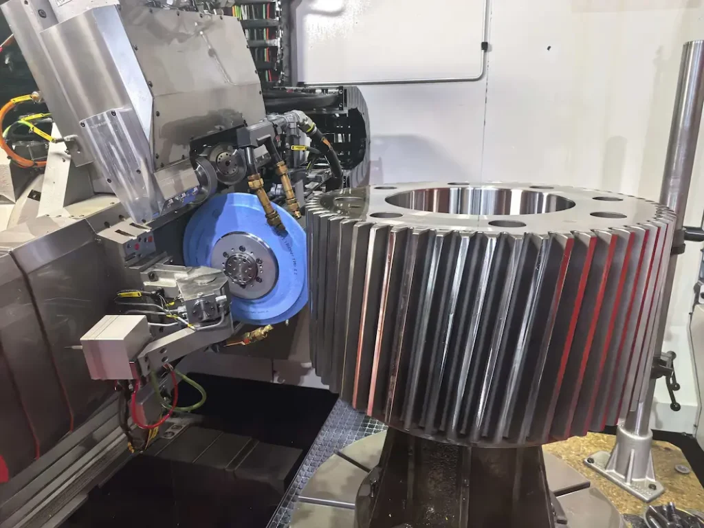
Helical gear grinding process
Gear Lapping
Gear lapping is a finishing process used mainly for bevel gears and high-precision transmission systems.
Benefits include:
- Improved tooth contact pattern
- Reduced surface roughness
- Lower operating noise
- Better load distribution
BELON combines gear cutting, heat treatment, grinding, lapping, and inspection processes to manufacture precision gears with optimized performance. See the following video to learn about gear lapping process:
Common Mistakes
Many engineers assume that gears can work together as long as the module is identical. This is one of the most common gear selection mistakes. Two gears with the same module may still fail to mesh properly because other parameters must also match.
Required matching parameters include:
Pressure Angle
The pressure angle determines:
- Tooth force direction
- Tooth thickness
- Load distribution
Different pressure angles cannot normally mesh correctly.
Number of Teeth
The tooth number affects:
- Gear ratio
- Center distance
- Tooth interference risk
Even with identical modules, different tooth combinations may create:
- Undercutting
- Poor contact ratio
- Excessive noise
Helix Angle
For helical gears, the helix angle must be considered.
The same module value can represent:
- Normal module
- Transverse module
Incorrect selection may cause:
- Wrong pitch diameter
- Incorrect center distance
- Gear meshing failure
Gear Accuracy Grade
Two gears with identical module and dimensions may still perform differently due to accuracy differences.
Gear accuracy affects:
- Noise
- Vibration
- Load distribution
- Service life
High-speed applications typically require higher accuracy grades such as:
- ISO 5–6
- AGMA 12–14
Standard industrial applications may use:
- ISO 7–8
- AGMA 10–12
Center Distance
The center distance must match the selected module and tooth numbers.
The basic relationship is:
Center Distance = (Number of Teeth 1 + Number of Teeth 2) × Module / 2
Incorrect center distance causes:
- Excessive backlash
- Tooth interference
- Reduced transmission efficiency
Module Selection Requires a Complete Gear Design Approach
The correct gear module is determined by the interaction of:
- Torque
- Load condition
- Speed
- Material strength
- Heat treatment
- Gear accuracy
- Manufacturing capability
- Application requirements
A professional gear manufacturer does not select module independently. Instead, engineers optimize the complete gear system, including tooth geometry, material, machining process, and inspection requirements.
Gear Module vs Diametral Pitch
Gear module and diametral pitch (DP) are two different systems used to define gear tooth size.
- Gear Module is the metric standard, widely used in Europe, Asia, and most modern gear manufacturing.
- Diametral Pitch (DP) is the imperial standard, commonly used in the United States and legacy machinery.
Although they describe the same gear tooth sizing concept, they use different measurement systems and are not directly interchangeable without conversion.
| Feature | Gear Module | Diametral Pitch (DP) |
| Measurement System | Metric | Imperial |
| Unit | mm | Teeth per inch |
| Definition | Pitch diameter divided by number of teeth | Number of teeth per inch of pitch diameter |
| Tooth Size Relationship | Larger module = larger teeth | Larger DP = smaller teeth |
| Common Usage | Modern industrial gears, automotive, machinery | US-designed equipment, replacement gears |
Module and DP Conversion
The relationship between module(m) and diametral pitch(DP) is:
- DP = 25.4 / m
- m = 25.4 / DP
For example:
A gear with module 2 is equivalent to: DP = 25.4 / 2 = 12.7 DP
When to Use Module or DP
Use Gear Module when:
- Designing new gear systems
- Manufacturing metric-based industrial equipment
- Working with ISO-standard gears
Use Diametral Pitch when:
- Replacing existing inch-based gears
- Maintaining legacy American machinery
- Working with US engineering drawings
Engineers should note that Module or DP Alone Does Not Define Gear Compatibility. Two gears cannot mesh correctly simply because their module or DP values match.
The following parameters must also be identical or compatible:
- Pressure angle
- Number of teeth
- Helix angle (for helical gears)
- Gear accuracy grade
- Center distance
Gear Module in Different Gear Types
Gear module is a fundamental parameter used in different gear systems, but its definition and application vary depending on the gear type.
Spur Gear Module

For spur gears, the module is the simplest and most commonly used gear sizing parameter.
The basic relationship is: Module = Pitch Diameter / Number of Teeth
For example, a spur gear with:
- Module: 4 mm
- Number of teeth: 40
will have:
Pitch diameter = 4 × 40 = 160 mm
Spur gear module selection mainly depends on:
- Transmitted torque
- Operating speed
- Material strength
- Required service life
- Available installation space
For precision spur gears, module selection should also consider manufacturing capability and accuracy requirements. High-precision applications may require gear grinding after heat treatment to achieve stable tooth contact and low noise operation.
Helical Gear Module
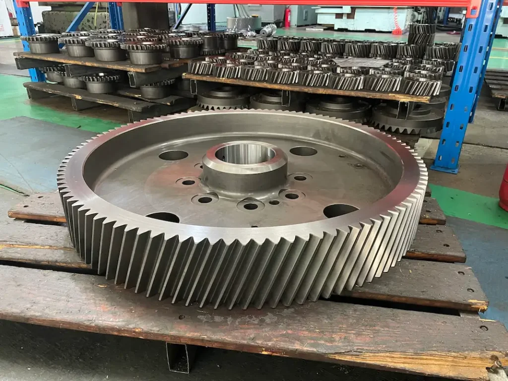
Helical gears use the same basic module concept as spur gears, but the presence of a helix angle introduces two different module definitions:
- Normal module (mn)
- Transverse module (mt)
Normal Module
The normal module is measured perpendicular to the tooth direction and is commonly used as the standard reference for helical gear manufacturing.
The relationship between normal module and transverse module is: mn = mt × cos β (β = Helix angle)
Because the normal tooth profile remains consistent with standard cutting tools, most helical gears are specified using normal module.
Bevel Gear Module

Bevel gears transmit power between intersecting shafts, commonly at 90° angles. Bevel gears have conical tooth geometry, so module selection must consider the gear cone structure.
For bevel gears, the module is generally defined at the large end of the tooth, where the tooth size is largest.
The module affects:
- Tooth strength
- Contact ratio
- Load capacity
- Gear dimensions
For high-performance bevel gears, module selection must be combined with material selection, heat treatment and tooth grinding or lapping
Worm Gear Module
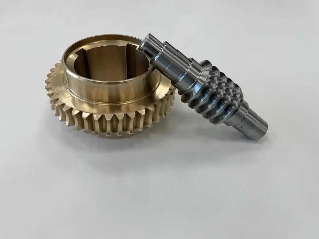
Worm gears use a different module concept because the worm and worm wheel operate through screw-like tooth engagement.
The module determines:
- Worm wheel tooth size
- Pitch diameter
- Load capacity
- Transmission ratio capability
For worm gears, module selection depends mainly on:
- Required torque
- Reduction ratio
- Operating speed
- Sliding conditions
- Lubrication requirements
Because worm gears experience significant sliding contact, material pairing is especially important. Common combinations include hardened steel worm + bronze worm wheel to improve wear resistance and reduce friction.
Gear Module Applications
Gear module plays an important role in determining gear strength, size, and load capacity. Different industries select different gear modules based on torque requirements, operating speed, space limitations, and service conditions.
The following table shows typical gear module applications across different industries.
| Industry | Common Gear Types | Typical Module Requirements | Image | Why Module Selection Matters |
| Industrial Gearboxes | Spur gears, Helical gears, Bevel gears, Worm gears | Medium to large modules (m3–m10+) | 
Worm gear set used in worm gearbox |
Industrial gearboxes require high torque capacity, long service life, and resistance to continuous loads. Larger modules provide stronger teeth and higher load capacity. |
| Robotics & Automation | Precision spur gears, Helical gears, Planetary gears | Small to medium modules (m0.5–m3) | 
Helical gear used in robotics planetary reducer |
Robots require compact size, low backlash, low noise, and high positioning accuracy. Smaller modules allow lightweight and precise transmission. |
| Automotive & EV | Helical gears, Spur gears, Bevel gears | Small to medium modules (m1–m4) | 
Automotive spiral bevel gear |
Automotive gears need a balance between strength, efficiency, weight, and noise control. |
| Agricultural Machinery | Spur gears, Bevel gears, Planetary gears | Medium to large modules (m3–m8+) | 
Spur gear set used agriculture machinery |
Agricultural equipment operates under variable and shock loads. Larger modules improve resistance to impact and tooth failure. |
| Mining Equipment | Heavy-duty helical gears, Bevel gears, Gear shafts | Large modules (m5–m20+) | 
Coal mining spiral bevel gear |
Mining machinery requires extremely high torque capacity and fatigue resistance. Large modules combined with hardened materials provide longer service life. |
| Marine Systems | Spiral bevel gears, Helical gears, Worm gears | Medium to large modules | 
Marine propeller gear |
Marine transmissions require high reliability, corrosion resistance, and continuous load capability. Module selection must consider torque and operating environment. |
| Wind Turbine Gearboxes | Planetary gears, Helical gears | Large modules | 
Bevel gears for wind turbine gearbox |
Wind turbines transmit high torque under fluctuating loads. Larger modules improve tooth strength and fatigue life. |
Gear Module Selection Depends on Application Requirements
Although module determines basic tooth size, the optimal module depends on the complete operating condition:
- High torque applications→ larger module for higher tooth strength
- High-speed applications→ smaller module with higher accuracy requirements
- Compact designs→ smaller module with optimized material strength
- Heavy-duty environments→ larger module combined with heat-treated alloy steel
BELON Custom Gear Module Solutions
Different industries require different gear designs. BELON provides customized gear manufacturing based on customer requirements, including:
- Spur gears
- Helical gears
- Spiral bevel gears
- Worm gear sets
- Gear shafts and spline shafts
BELON helps customers select the appropriate module, material, and manufacturing process to achieve reliable transmission performance.
BELON Manufactures Precision Module Gears
Selecting the correct gear module is only the first step. The actual performance of a gear depends on how accurately the gear is manufactured, heat treated, finished, and inspected.
At BELON, we manufacture custom module gears through a complete in-house production process, from raw material preparation to final inspection. This integrated manufacturing capability allows us to control gear quality, accuracy, and consistency for different industries and OEM requirements. Belon has good expertise in:
✓ Custom module gear design
✓ Precision gear machining
✓ Heat treatment control
✓ ISO / DIN / AGMA standards
✓ OEM production support
✓ Small and large batch manufacturing
Contact BELON today to discuss your custom gear requirements and find the right module solution for your application.
FAQs
What is the gear module?
Gear module is a parameter used to define the size of gear teeth in the metric system. It represents the relationship between the pitch diameter and the number of teeth.
The formula is:
Module = Pitch Diameter / Number of Teeth
A larger module means larger teeth, which generally provides:
- Higher load-carrying capacity
- Greater tooth bending strength
- Better resistance to shock loads
However, a larger module also increases gear size and weight. Therefore, module selection must balance strength, space limitations, speed, and application requirements.
How can I identify the module of an existing gear?
The module of an existing gear can be identified through several methods:
- Measure the Gear Dimensions
If the pitch diameter and tooth number are known: Module = Pitch Diameter / Number of Teeth
- Measure Tooth Pitch
The circular pitch can also be used: Module = Circular Pitch / π
- Check Existing Drawings or Specifications
For OEM replacement gears, the module is usually listed on:
-
- Engineering drawings
- Gear inspection reports
- Manufacturer specifications
When replacing an unknown gear, it is also necessary to confirm:
-
- Pressure angle
- Number of teeth
- Helix angle
- Face width
- Accuracy grade
Matching only the module is not enough to ensure proper meshing.
Do meshing gears need the same module?
Yes. Two standard gears must have the same module to mesh correctly.
However, the module alone does not guarantee compatibility.
Meshing gears must also have matching or compatible:
- Pressure angle
- Tooth profile
- Number of teeth
- Helix angle (for helical gears)
- Center distance
- Gear accuracy grade
For example, two gears with the same module but different pressure angles may experience incorrect tooth contact, increased noise, and premature failure.
What gear module should I choose?
The correct gear module depends on the operating requirements, including:
- Torque
- Load conditions
- Speed
- Material
- Available installation space
- Required service life
General guidelines:
| Application | Recommended Module Consideration |
| High torque and heavy loads | Larger module for higher tooth strength |
| High-speed precision systems | Smaller module with higher accuracy |
| Compact equipment | Smaller module with optimized materials |
| Shock-load applications | Larger module with stronger materials |
For demanding applications, module selection should be combined with tooth width, material selection, heat treatment, and manufacturing process.
What causes gear tooth failure?
Gear tooth failure is usually caused by excessive stress, improper design, or unsuitable operating conditions.
Common failure modes include:
- Tooth Breakage
Caused by:
-
- Excessive torque
- Shock loading
- Insufficient tooth strength
- Incorrect module selection
- Pitting and Surface Fatigue
Caused by:
-
- High contact stress
- Poor lubrication
- Insufficient surface hardness
- Wear
Caused by:
-
- Poor lubrication
- Contamination
- Incorrect tooth contact
- Scuffing
Caused by:
-
- Excessive sliding speed
- High temperature
- Lubrication failure
Preventing gear failure requires proper module selection, suitable materials, accurate machining, and correct heat treatment.
Can damaged gears be repaired?
In some cases, damaged gears can be repaired, but it depends on the failure condition and damage severity.
Possible repair methods include:
- Gear grinding for minor surface damage
- Tooth profile correction
- Re-machining for limited wear
- Heat treatment restoration in specific cases
However, gears with broken teeth, severe pitting, cracks and significant deformation usually require replacement.
For critical equipment, replacing a damaged gear with a newly manufactured precision gear is often more reliable and cost-effective.
BELON supports OEM replacement gears and customized gear manufacturing based on:
- Existing samples
- Drawings
- Gear measurements
- Application requirements