
Abstract: Learn what a rack and pinion system is, its types, how it works, and where it’s used in industrial applications — plus how to choose the suitable custom rack and pinion manufacturer.
What is a rack and pinion ?

A rack and pinion is a mechanical system that converts rotary motion into linear motion (and vice versa). It consists of two components: a rack (a flat, straight gear with teeth along its length) and a pinion (a small circular gear that meshes with the rack). When the pinion rotates, its teeth engage the rack and push it in a straight line. When the rack moves linearly, it drives the pinion to rotate.
This simple but highly effective mechanism has been used in engineering for centuries and remains one of the most widely applied power transmission solutions in modern industry.
How Does a Rack and Pinion Work?
The working principle is simple:
- The pinion is mounted on a rotating shaft and driven by a motor or manual input.
- The rack is positioned linearly alongside the pinion, with its teeth meshing directly with the pinion teeth.
- As the pinion rotates clockwise, the rack moves in one direction. Rotating the pinion counterclockwise moves the rack in the opposite direction.
This two-way motion conversion makes rack and pinion systems highly versatile. In some configurations, the rack remains stationary while the pinion moves along it. In others, the pinion is fixed and the rack slides past it. The design depends on the application requirement.
Types of Rack and Pinion Gears
There are various types of rack and pinion gears, primarily distinguished by tooth geometry:
Spur Rack and Pinion

The most common type. Teeth are cut straight and parallel to the rack axis. This type is easy to manufacture, cost-effective, and suitable for moderate-speed applications. Widely used in industrial machinery, material handling, and lifting equipment.
Helical Rack and Pinion

Teeth are cut at an angle, producing smoother and quieter operation compared to spur racks. Because the load is distributed across multiple teeth simultaneously, this helical drive system is ideally suited for CNC machine tools, robotics, and precision automation equipment that demand exceptional motion smoothness.
Pneumatic and Hydraulic Rack and Pinion Actuators
In these systems, the rack is driven by pneumatic or hydraulic pressure rather than a motor.They are commonly used in valve actuators, quarter-turn control systems, and industrial automation applications.
Key Advantages of Rack and Pinion Gears
Compared to other linear motion solutions such as ball screws, belts, or hydraulic cylinders, rack and pinion drives offer several advantages:
- Unlimited stroke length— Racks can be joined end-to-end to achieve virtually any travel distance, which ball screws cannot.
- High load capacity— Direct tooth engagement allows rack and pinion gears toefficiently transmit massive forces
- High speed capability— Suitable for fast linear motion that exceed the limits of ball screws.
- Simple structure— Fewer components mean easier installation and reduced maintenance requirements.
- Bidirectional motion— The system can convert motion in both directions without additional components.
Industrial Applications of Rack and Pinion
Automotive Steering

This is the most widely recognized application. Rack and pinion steering converts the rotation of the steering wheel into the lateral movement of the front wheels. Its compact size, direct response, and reliability have made it the dominant steering system in modern passenger vehicles.
CNC Machining and Automation
CNC routers, plasma cutters, laser cutting machines, and gantry systems rely heavily on rack and pinion drives for achieve long-stroke, high-speed linear motion. Helical rack and pinion systems are preferred in these applications for their smooth operation and accurate positioning.
Robotics
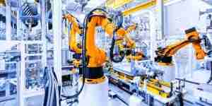
Rack and pinion mechanisms are used in robotic arms, automated guided vehicles (AGVs), and linear actuators to achieve precise and repeatable linear motion.
Construction and Heavy Equipment

Cranes, excavators, drilling rigs, and tunnel boring machines use large rack and pinion drives to handle high torque and significant linear forces in demanding environments.
Railway Systems
On steep sections where conventional wheel-rail traction is insufficient, rack railways use a toothed rack between the rails and a pinion underneath the locomotive to provide the additional traction needed to climb the slope safely.
Elevators and Lifting Systems
Rack and pinion lifting systems are used in construction elevators, ski lifts, and material hoists where reliable vertical motion is required without the complexity of cable systems.
How to Choose the Suitable Rack and Pinion Gears
When selecting rack and pinion gears, consider the following factors:
- Load requirement— Calculate the maximum linear force the system must transmit to determine the required module and tooth size.
- Speed and precision— High-speed or high-accuracy applications typically require helical racks with ground tooth surfaces.
- Stroke length— For long travel distances, confirm whether rack sections need to be joined and how joints will be managed to maintain accuracy.
- Material— Steel is standard for industrial rack and pinion systems. Stainless steel or plastic may be selected for corrosive environments or light-duty applications.
- Backlash requirement— Applications requiring tight positioning accuracy need anti-backlash designs or precision-ground racks and pinions.
- Surface hardness— For heavy-load or high-cycle applications, heat treatment and surface hardening are critical to extending service life.
Custom Rack and Pinion Manufacturing at Belon
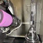
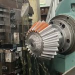
At Belon, we manufacture custom rack and pinion components to meet exact specifications. From module selection and tooth geometry to material, heat treatment, and surface finish, every detail is engineered and machined to drawing requirements. See the following video to check how racks are manufactured in Belon’s workshop:
Whether you need a single prototype or volume production, our precision manufacturing capabilities cover spur and helical rack and pinion gears for industrial automation, CNC equipment, robotics, and heavy machinery applications. Contact our engineering team today!
FAQs
Q1: What is the difference between a spur rack and a helical rack?
A spur rack has straight teeth parallel to the rack axis, making it simpler and more cost-effective to manufacture. A helical rack has angled teeth, which produces smoother and quieter operation with better load distribution. Helical racks are preferred for high-speed or precision applications such as CNC machines and robotics.
Q2: What materials are rack and pinion gears typically made of?
The most common material is steel, including alloy steels such as 42CrMo4 or 20CrMnTi, which offer a good balance of strength and machinability. Stainless steel is used in corrosive environments, and engineering plastics such as nylon or POM are used in light-load or low-noise applications.
Q3: How is backlash controlled in rack and pinion?
Backlash can be reduced through precision grinding of tooth surfaces, tighter manufacturing tolerances, anti-backlash pinion designs, or spring-loaded dual-pinion configurations. The specific approach depends on the positioning accuracy required by the application.
Q4: Can rack sections be joined together for long travel distances?
Yes. Racks can be manufactured in standard lengths and joined end-to-end to achieve any required stroke length. For precision applications, the joints between rack sections must be carefully aligned and machined to avoid positioning errors at the connection points.
Q5: What is the typical accuracy grade for industrial rack and pinion gears?
Industrial rack and pinion gears are typically manufactured to DIN or ISO accuracy grades. Precision-ground racks can achieve DIN Grade 4 or better, while standard hobbed racks typically fall within the DIN 7–9 range. The required grade depends on the positioning accuracy and load requirements of the application.