

Abstract: A worm and worm wheel is a compact gear transmission system widely used for high reduction ratios, smooth power transmission, and right-angle motion in industrial machinery. This guide explains definition, how a worm and worm wheel works, its main components, transmission principles, velocity ratio, material selection, and self-locking characteristics.
What Is a Worm and Worm Wheel?
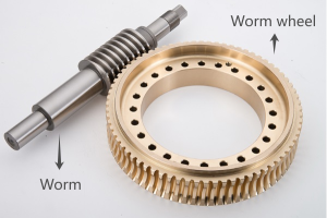
A worm and worm wheel is a right-angle gear transmission consisting of a screw-like worm and a toothed worm wheel. It converts rotary motion into reduced-speed, high-torque output.
Compared with conventional gear pairs, this configuration can achieve much higher reduction ratios in a compact space.
Worm
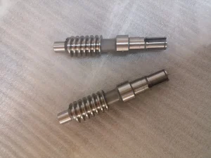
The worm is a cylindrical shaft with one or more helical threads machined along its outer surface, giving it an appearance similar to a precision screw. It serves as the driving element in the gear set and is usually manufactured from hardened alloy steel to withstand continuous sliding contact and high surface loads. Depending on the required transmission ratio and operating efficiency, worms can be designed with single-start or multiple-start threads.
Worm Wheel
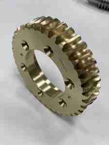
The worm wheel is the driven gear that meshes with the worm. Its specially shaped teeth partially wrap around the worm threads, creating a larger contact area than most conventional gear pairs. Because the engagement is dominated by sliding rather than rolling, the worm wheel is commonly manufactured from wear-resistant bronze alloys, while the worm is made from hardened steel. This material combination helps minimize friction, reduce wear, and extend service life.
How Does a Worm and Worm Wheel Work?
A worm drive transmits motion through the continuous engagement between the helical threads of the worm and the specially shaped teeth of the worm wheel. The worm gear transmission operates through a combination of rolling and sliding motion, with sliding being the dominant form of contact. This unique meshing mechanism enables the gear set to achieve high reduction ratios, smooth operation, and efficient right-angle power transmission within a compact design. See the following video to check how worm and worm wheel work together:
When the driving motor rotates the worm, its screw-like threads progressively engage the teeth of the worm wheel. Each revolution of the worm advances the wheel by a specific number of teeth, determined by the number of worm starts. For example, a single-start worm driving a 40-tooth wheel produces a 40:1 reduction ratio, meaning the worm must complete forty revolutions for the wheel to rotate once. This substantial speed reduction is accompanied by a proportional increase in output torque, making worm gears particularly suitable for heavy-duty applications where high torque and low output speed are required.
Sliding Contact
The worm thread continuously slides across the tooth surface of the worm wheel instead of rolling against it. This sliding motion ensures smooth and quiet operation while allowing high reduction ratios. However, it also increases friction and heat generation, so hardened steel worms, bronze worm wheels, and high-performance lubricants are commonly used to reduce wear and improve efficiency.
Right-Angle Power Transmission
A worm gear set transfers power between two shafts that are typically positioned at 90 degrees. This compact arrangement eliminates the need for additional transmission components and is widely used in conveyors, lifting equipment, valve actuators, and industrial gearboxes where space-saving layouts are required.
Torque Multiplication
As the worm rotates, the worm wheel turns much more slowly, producing a high reduction ratio. The reduction in speed is accompanied by a proportional increase in output torque, enabling relatively small motors to drive heavy loads efficiently. Depending on the gear ratio and operating conditions, many worm gear drives can also provide a useful self-locking function that prevents reverse motion.
Velocity Ratio Calculation of Worm and Worm Wheel
The velocity ratio of a worm and worm wheel, also known as the worm gear ratio, describes the relationship between the rotational speed of the worm and that of the worm wheel. It determines how much the input speed is reduced and how much output torque is increased. In general, a higher gear ratio results in lower output speed but greater torque, making worm gear drives ideal for applications requiring precise motion control and heavy load transmission.
Usually, the velocity ratio of a worm gear depends on only two parameters: the number of starts on the worm and the number of teeth on the worm wheel. This simple relationship makes worm gear design both predictable and easy to optimize for different applications.
Formula
The worm gear ratio is calculated using the following equation:
Velocity Ratio (i) = Z₂ / Z₁
Where:
- Z₁= Number of starts (threads) on the worm
- Z₂= Number of teeth on the worm wheel
A single-start worm advances the wheel by one tooth per revolution, while a multi-start worm advances it by two or more teeth. Therefore, increasing the number of worm starts reduces the overall reduction ratio but increases output speed and transmission efficiency.
Example Calculation
Suppose a worm gear set consists of:
- Worm starts (Z₁) = 1
- Worm wheel teeth (Z₂) = 40
The velocity ratio is calculated as:
i = 40 ÷ 1 = 40:1
This means the worm must rotate 40 revolutions for the worm wheel to complete one full revolution. As a result, the output shaft rotates at one-fortieth of the input speed while delivering significantly higher torque.
If the same 40-tooth worm wheel is paired with a 2-start worm, the ratio becomes 20:1, increasing the output speed but reducing the torque multiplication.
Factors Affecting Ratio
Several design parameters influence the velocity ratio of a worm and worm wheel and the overall performance of the gear set.
- Number of Worm Starts– The primary factor affecting the gear ratio. Single-start worms provide higher reduction ratios, while multi-start worms offer faster output speeds and better efficiency.
- Number of Wheel Teeth– Increasing the number of teeth on the worm wheel raises the reduction ratio, producing lower output speed and greater torque.
- Lead Angle– A larger lead angle generally improves transmission efficiency and reduces friction but also decreases the potential reduction ratio and self-locking capability.
When selecting a worm gear set, engineers should balance reduction ratio, efficiency, torque requirements, and operating conditions to achieve the desired performance.
Table 1. Relationship Between Worm Starts and Gear Ratio
| Worm Starts | Worm Wheel Teeth | Worm Gear Ratio | Typical Characteristics | Worm Starts |
| 1 | 40 | 40:1 | High torque, low speed, possible self-locking | 1 |
| 2 | 40 | 20:1 | Balanced speed and efficiency | 2 |
| 4 | 40 | 10:1 | Higher speed, improved efficiency | 4 |
| 6 | 40 | 6.7:1 | Fast output, lower torque multiplication | 6 |
Types of Worm Gears
Worm gear sets are available in several configurations to meet different requirements for speed reduction, efficiency, load capacity, and backlash control. Selecting the appropriate worm type depends on factors such as transmission ratio, operating conditions, positioning accuracy, and service life. The following are the most common types used in industrial power transmission. [Request A Quote Now]
Single-start Worm
A single-start worm has one continuous thread wrapped around the worm shaft. Because the worm wheel advances by only one tooth for each revolution of the worm, it provides a high reduction ratio and excellent load-holding capability. This design is widely used in hoists, lifting platforms, and speed reducers where low output speed and self-locking characteristics are important.
Multi-start Worm
A multi-start worm features two or more threads running along the shaft. With each revolution, the worm wheel advances multiple teeth, resulting in a lower reduction ratio but higher transmission efficiency and faster output speed. Multi-start worms are commonly selected for conveyors, packaging machinery, and automation equipment that require smooth motion and continuous operation.
Duplex Worm
A duplex worm has a gradually changing tooth thickness along its threaded length, allowing backlash to be adjusted by moving the worm axially during assembly. This design helps compensate for wear over time and maintains accurate gear meshing without replacing the entire gear set. Duplex worms are often used in precision indexing systems, machine tools, and other applications where positioning accuracy is critical.
Hourglass Worm
An hourglass worm, also known as a double-enveloping worm, has a curved profile that wraps around the worm wheel, creating a larger tooth contact area than a conventional cylindrical worm. The increased contact improves load distribution, torque capacity, and transmission efficiency while reducing surface pressure and wear. Hourglass worm gears are commonly used in heavy-duty industrial gearboxes, mining equipment, and high-power transmission systems.
Worm Gear Materials
Selecting the right worm gear materials is essential for achieving high transmission efficiency, long service life, and reliable performance. In real life, the worm and worm wheel are rarely manufactured from the same material. Because the gear pair operates primarily through sliding contact, using dissimilar materials helps minimize friction, prevent adhesive wear, and improve heat dissipation.
In most industrial applications, a hardened steel worm paired with a bronze worm wheel is often selected by gear manufacturers. This combination offers an excellent balance of strength, wear resistance, and anti-scuffing properties. However, depending on the operating load, speed, and working environment, other materials such as aluminum bronze, cast iron, engineering plastics, or carbon steel may also be selected.
Hardened Steel Worm
A steel worm is typically manufactured from alloy steels such as 20CrMnTi, 42CrMo, or AISI 8620, followed by carburizing, quenching, and precision grinding. The hardened surface ensures excellent wear resistance and sufficient strength to withstand continuous sliding loads.
Because the worm experiences the highest contact stress during operation, high surface hardness is essential for reducing wear and maintaining stable tooth geometry over long service periods.
Bronze Worm Wheel
A bronze worm wheel is the most common choice for industrial worm gear drives due to its excellent anti-friction and anti-seizure properties. Tin bronze (such as CuSn12) provides good compatibility with hardened steel, and can reduce the risk of galling while maintaining smooth meshing under heavy loads.
Bronze also has good thermal conductivity, helping dissipate the heat generated by sliding contact. For these reasons, it remains the preferred material for gear reducers, conveyors, lifting equipment, and other continuously operating machinery.
Aluminum Bronze
For heavy-duty or shock-load applications, aluminum bronze offers higher mechanical strength than conventional tin bronze while maintaining good wear resistance. The worm gear made of this material is commonly used in mining equipment, marine drives, and large industrial gearboxes where higher loads and longer service life are required.
Although aluminum bronze is generally more expensive, its superior strength and durability often justify the additional cost in demanding environments.
Cast Iron
Cast iron was widely used in traditional worm gear systems because of its good machinability, vibration damping, and relatively low manufacturing cost. Today, however, it is less common in modern high-performance gearboxes due to its lower wear resistance compared with bronze alloys.
Cast iron worm wheels may still be found in light-duty machinery or legacy equipment where operating speeds and loads are relatively low.
Table 2. Common Materials for Worm and Worm Wheel
| Component | Material | Key Characteristics | Typical Applications |
| Worm | Acetal / Nylon | Lightweight, low cost, suitable for light-duty service | Toys, household appliances, small instruments |
| Cast Iron | Good machinability and vibration damping | Low-speed or legacy machinery | |
| Carbon Steel | Moderate strength and economical | General industrial drives with medium loads | |
| Hardened Alloy Steel | High hardness, excellent wear resistance, long service life | Industrial gearboxes, conveyors, lifting equipment | |
| Worm Wheel | Acetal / Nylon | Quiet operation and low friction for light loads | Consumer products and small automation devices |
| Tin Bronze (Phosphor Bronze) | Excellent wear resistance, low friction, compatible with hardened steel | Standard industrial worm gear reducers | |
| Aluminum Bronze | Higher strength and load capacity than tin bronze | Mining equipment, marine drives, heavy-duty gearboxes | |
| Cast Iron | Economical and easy to machine, suitable for low-speed applications | Older machinery and light-duty equipment |
Why Are Worm Wheels Usually Made of Bronze?
A bronze worm wheel is commonly paired with a hardened steel worm because worm gears transmit power through continuous sliding contact rather than rolling contact. This operating principle generates more friction and heat than other gear types, making material selection critical. Using two different materials reduces wear, improves lubrication, and extends the service life of the gear set
1. Better Wear Resistance
Bronze is softer than hardened steel, allowing it to absorb minor wear without damaging the worm. Since the worm wheel is generally easier and less expensive to replace, this combination reduces long-term maintenance costs.
2. Lower Risk of Galling
A steel worm sliding against a bronze worm wheel is much less likely to seize than two steel components. Bronze has excellent anti-scuffing properties, helping maintain smooth tooth engagement under heavy loads.
3. Improved Lubrication
Bronze works well with industrial gear oils and helps maintain a stable lubricant film between the mating surfaces. This reduces friction, limits heat generation, and improves transmission efficiency.
4. Longer Service Life
The combination of a hardened steel worm and a bronze wheel provides an excellent balance between strength and durability. The steel worm resists deformation, while the bronze wheel accommodates wear, resulting in reliable performance over long operating periods.
Table 3. Common Material Combinations for Worm Gears
| Material Combination | Friction & Wear | Typical Applications |
| Steel Worm + Bronze Worm Wheel | Low friction, excellent wear resistance | Industrial gearboxes, conveyors, lifting equipment |
| Steel Worm + Steel Worm Wheel | High friction, prone to galling | Rarely used for continuous-duty applications |
| Bronze Worm + Bronze Worm Wheel | Lower strength and load capacity | Light-duty or special-purpose equipment |
| Steel Worm + Plastic Worm Wheel | Quiet operation and lightweight | Household appliances, instruments, light automation |
How to Design a Worm and Worm Wheel
A successful worm gear design requires more than simply selecting a gear ratio. Designers must balance strength, efficiency, durability, and manufacturing accuracy while considering the application’s speed, torque, operating environment, and service life. The following design parameters have the greatest influence on the performance of a worm gear set.
Module
The module (m) determines the size of the gear teeth and directly affects load capacity. A larger module produces stronger teeth capable of transmitting higher torque, while a smaller module enables a more compact gearbox with smoother operation. The module should always be selected according to the required torque and available installation space.
Pressure Angle
The pressure angle influences tooth strength, contact stress, and meshing characteristics. Common values include 20° and 25°, with 20° being the most widely used for industrial worm gears. A suitable pressure angle helps improve load distribution and ensures stable power transmission.
Lead Angle
The lead angle is the angle between the worm thread and its axis. It has a significant effect on transmission efficiency and self-locking performance. A larger lead angle generally improves efficiency and reduces sliding friction, while a smaller lead angle increases the possibility of self-locking for lifting and positioning applications.
Center Distance
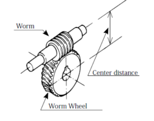
The center distance is the distance between the axes of the worm and the worm wheel. It determines the overall gearbox size and affects tooth contact, load distribution, and gear strength. Accurate center distance is essential for proper meshing and long service life.
Backlash
Worm gear backlash is the clearance between the mating tooth surfaces. A small amount of backlash is necessary to accommodate lubrication, thermal expansion, and manufacturing tolerances. Excessive backlash may reduce positioning accuracy and increase vibration, while insufficient backlash can cause overheating and premature wear.
Efficiency
Transmission efficiency depends on several factors, including the gear ratio, lead angle, surface finish, lubrication quality, and manufacturing accuracy. Optimizing these parameters helps reduce friction losses, improve power transmission, and lower operating costs.
Heat Generation
Worm gears operate primarily through sliding contact, with limited rolling action depending on the geometry. High-speed or heavily loaded gearboxes may require improved lubrication, cooling systems, or optimized gear geometry to control operating temperature and maintain long-term reliability.
Table 4. Key Design Parameters for Worm Gears
| Design Parameter | Function | Design Consideration |
| Module | Determines tooth size and strength | Match with required torque and gearbox size |
| Pressure Angle | Affects tooth strength and contact | 20° is commonly used in industrial applications |
| Lead Angle | Influences efficiency and self-locking | Larger angle improves efficiency; smaller angle enhances self-locking |
| Center Distance | Defines gearbox dimensions and meshing | Maintain precise alignment for even load distribution |
| Worm Gear Backlash | Provides operating clearance | Balance lubrication, accuracy, and thermal expansion |
| Transmission Efficiency | Determines power loss | Improve through optimized geometry, surface finish, and lubrication |
| Heat Generation | Affects durability and lubricant life | Control with proper lubrication and thermal management |
Lubrication and Maintenance
Proper worm gear lubrication is essential for maintaining transmission efficiency and extending the service life of a worm gear set. Because the worm and worm wheel operate through continuous sliding contact, they generate more friction and heat than most other gear types. Selecting the correct lubricant, monitoring operating temperature, and following a regular maintenance schedule can significantly reduce wear and improve gearbox reliability.

1. Select the Right Lubricant
Worm gear drives typically use industrial gear oils with high film strength to protect the sliding tooth surfaces. The lubricant should provide excellent anti-wear performance, oxidation resistance, and thermal stability for continuous operation.
2. Choose the Appropriate ISO VG Grade
The viscosity of the lubricant should match the operating speed and load.
Table 5. Recommended ISO VG grade for operation conditions
| Operating Condition | Recommended ISO VG |
| High-speed, light load | ISO VG 220 |
| Medium-speed, general applications | ISO VG 320 |
| Low-speed, heavy load | ISO VG 460–680 |
3. Use EP Additives
Lubricants containing Extreme Pressure (EP) additives provide additional protection under heavy loads by reducing metal-to-metal contact. However, when using a bronze worm wheel, ensure the lubricant is compatible with copper alloys to prevent chemical corrosion.
4. Control Operating Temperature
Excessive heat accelerates lubricant degradation and increases gear wear. For most industrial worm gearboxes, the oil temperature should ideally remain below 90°C during continuous operation. If temperatures rise significantly, consider improving cooling, reducing load, or selecting a lubricant with higher thermal stability.
5. Perform Regular Maintenance
Routine maintenance helps identify problems before they lead to gearbox failure. A preventive maintenance program should include:
- Check the oil level regularly.
- Replace lubricant at the recommended service interval.
- Inspect for oil leakage or contamination.
- Monitor abnormal noise, vibration, and temperature.
- Examine gear tooth wear during scheduled overhauls.
Common Applications
The uses of worm and worm wheel span a wide range of industries where high reduction ratios, high output torque, compact right-angle transmission, and smooth operation are required. Their ability to combine speed reduction with precise motion control makes worm gear drives a preferred solution for both heavy-duty industrial equipment and precision automation systems.
Table 6. Common Applications of Worm and Worm Wheel
| Industry | Typical Application | Why Worm Gears Are Used |
| Material Handling | Conveyor reducers | High torque output and reliable continuous operation |
| Lifting Equipment | Hoists, winches, lifting platforms | High reduction ratio and self-locking capability |
| Packaging Machinery | Indexing tables, filling and sealing machines | Smooth, accurate, and low-noise transmission |
| Food & Beverage | Processing equipment and production line drives | Compact design with stable low-speed operation |
| Mining & Cement | Gearboxes, crushers, conveyors | Handles heavy loads and high torque requirements |
| Valve Actuation | Electric and manual valve actuators | Precise positioning and resistance to back-driving |
| Robotics & Automation | Compact gear drives, rotary positioning units | Space-saving design with accurate motion control |
| Machine Tools | Rotary tables, feed mechanisms | Stable transmission and precise speed reduction |
| Agricultural Machinery | Seeders, irrigation systems, harvesting equipment | Durable operation in demanding environments |
| Marine Equipment | Deck machinery, steering systems | Reliable transmission under continuous heavy-duty service |
Manufacturing Process of Precision Worm and Worm Wheels
The performance of a precision worm gear depends not only on its design but also on the manufacturing process. High machining accuracy, proper heat treatment, and strict quality inspection all contribute to smooth meshing, high transmission efficiency, and long service life. At BELON, every custom worm gear is manufactured through a controlled production process to ensure consistent quality and reliable performance for demanding industrial applications.
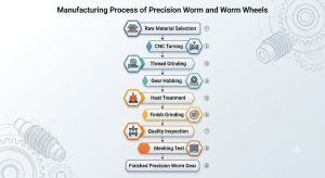
1. Raw Material Selection
Production begins with selecting the appropriate material based on the application. Hardened alloy steels are commonly used for worms, while bronze alloys are preferred for worm wheels because of their excellent wear resistance and compatibility with sliding contact.
2. CNC Turning
The worm shaft and gear blank are precision turned to achieve the required dimensions, concentricity, and surface finish. This operation provides the foundation for accurate tooth machining.
3. Thread Grinding
The worm threads are ground to achieve precise lead accuracy and excellent surface quality. High-precision grinding reduces friction, improves tooth contact, and enhances transmission efficiency.
4. Gear Hobbing
The worm wheel teeth are generated using dedicated hobbing machines to ensure accurate tooth geometry and proper meshing with the mating worm. Tight machining tolerances are essential for stable operation and low noise.
5. Heat Treatment
Depending on the material and performance requirements, processes such as carburizing, quenching, tempering, or nitriding are applied to improve surface hardness, wear resistance, and fatigue strength.
6. Finish Grinding
After heat treatment, critical surfaces are finish-ground to remove distortion and achieve the required dimensional accuracy. This step helps ensure smooth transmission and consistent tooth contact.
7. Inspection
Each component undergoes comprehensive quality inspection, including dimensional measurement, tooth profile verification, hardness testing, and runout inspection. Advanced measuring equipment ensures every gear meets the specified quality standard.
8. Meshing Test
Before delivery, the worm and worm wheel are assembled for a meshing test to verify contact pattern, backlash, transmission smoothness, and operating noise. This final validation ensures reliable performance under real operating conditions.
How to Select a Worm Gear Manufacturer
A qualified worm gear supplier should provide not only precision manufacturing but also engineering support, material recommendations, and quality control throughout the production process. When selecting a worm gear manufacturer, consider these key factors:
1. Manufacturing Experience and Gear Expertise
An experienced worm gear manufacturer should understand critical design factors such as tooth profile, lead angle, center distance, backlash, gear ratio, and contact pattern.
A professional supplier can help optimize:
- Worm and worm wheel tooth design
- Load capacity and torque requirements
- Material combinations
- Lubrication and operating conditions
Beyond standard products, experienced manufacturers can provide customized worm gear solutions based on specific application requirements.
2. Manufacturing Capabilities and Precision Control
Worm gear performance depends heavily on machining accuracy and finishing quality. A reliable manufacturer should have complete production capabilities, including:
- Precision worm and worm wheel machining
- Heat treatment for improved strength and wear resistance
- Surface finishing to reduce friction and improve tooth contact
- Gear inspection for profile accuracy, backlash, lead accuracy, and dimensional control
3. Material Selection and Heat Treatment Knowledge
The right material combination directly affects efficiency, durability, and operating noise.
Common solutions include:
- Hardened steel worms for high strength and wear resistance
- Bronze worm wheels for excellent sliding performance and reduced friction
- Steel worm wheels for high-load applications
A capable supplier should recommend suitable materials and heat treatment methods based on load, speed, temperature, and duty cycle.
4. Quality Control and OEM Support
A reliable worm gear manufacturer should follow international standards such as ISO, DIN, or AGMA and perform strict inspections on:
- Tooth profile and lead accuracy
- Backlash and runout
- Surface hardness
- Tooth contact pattern
- Dimensional accuracy
For customized projects, manufacturers should also provide engineering support, including reverse engineering, design optimization, prototyping, and OEM production.
BELON Worm Gear Manufacturing Capabilities
BELON Machinery provides customized worm gear and worm wheel solutions for industrial transmission applications. From design support to final inspection, we help customers develop reliable and application-specific gear components.
Our capabilities include:
- Custom worm gear manufacturing based on drawings, samples, or technical requirements
- Complete production support including machining, heat treatment coordination, finishing, and inspection
- Material selection assistance for optimized performance and durability
- Precision machining to ensure accurate tooth geometry and smooth meshing
- OEM and small-batch production for customized industrial applications
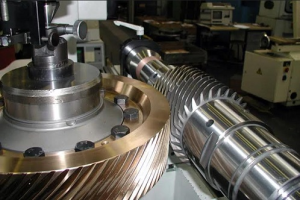
In addition to worm gears, BELON manufactures precision spur gears, helical gears, bevel gears, gear shafts, and custom gearbox components. This integrated manufacturing capability allows us to provide complete transmission solutions for industrial equipment manufacturers.
Whether for replacement parts or new OEM projects, BELON works with customers to deliver reliable worm gear solutions tailored to specific operating requirements.
Ready to Customize Your Worm Gear Solution?
Send us your worm gear drawing, gearbox specifications, or existing sample. Our engineers can recommend suitable materials, machining processes, and accuracy grades based on your application requirements. Contact BELON today or send email to marketing@belongear.com to discuss your project and receive expert engineering support and a customized quotation.
FAQs
Q1: What is a worm and worm wheel?
A worm and worm wheel is a gear set consisting of a worm (a screw-like gear) and a worm wheel (a toothed gear) that transmit motion between two shafts, usually positioned at a 90° angle. The worm drives the wheel through sliding contact, providing high reduction ratios and smooth, quiet operation.
Q2: How does a worm and worm wheel work?
A worm and worm wheel works by converting the rotary motion of the worm into rotary motion of the worm wheel. As the worm rotates, its helical threads push against the teeth of the worm wheel, causing the wheel to rotate at a slower speed while increasing torque.
Q3: How is power transmitted from a worm and worm wheel?
Power is transmitted through the meshing contact between the worm threads and worm wheel teeth. The worm applies a tangential force to the wheel teeth, transferring torque from the driving shaft to the driven shaft. Due to sliding contact, worm gears provide smooth operation but have lower efficiency than many other gear types.
Q4: How to calculate the gear ratio of a worm and worm wheel?
The gear ratio of a worm and worm wheel is calculated by:
Gear Ratio = Number of Worm Wheel Teeth ÷ Number of Worm Starts
For example, a worm wheel with 40 teeth driven by a single-start worm has a 40:1 reduction ratio.
Q5: Why are worm wheels made of bronze?
Worm wheels are often made of bronze because it provides excellent wear resistance, low friction, and good compatibility with steel worms. The softer bronze material reduces friction, prevents seizure, and helps extend the service life of the worm gear set.