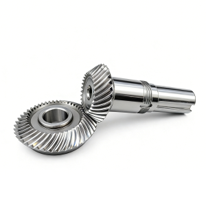
Application of Spiral Bevel Gear in Excavators
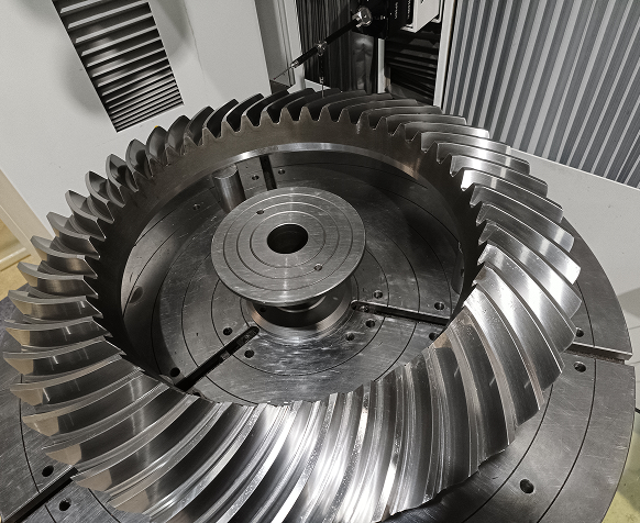
Spiral Bevel Gears are primarily used in excavators at locations requiring intersecting shaft (typically 90°) direction change combined with high-torque speed reduction. They are mainly applied in the following three core positions:
Application Locations of Spiral Bevel Gear in Excavators
1. Final Drive / Travel Reducer
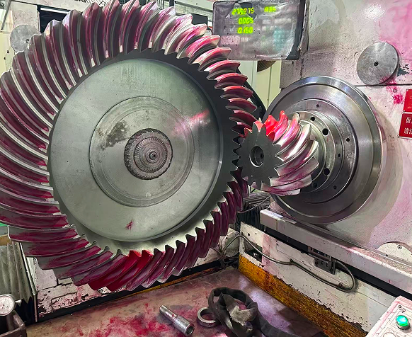
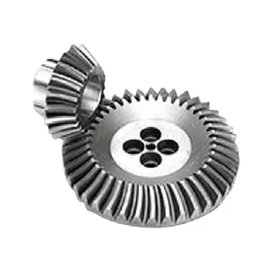
The power output from the hydraulic travel motor passes through the first-stage spiral bevel gear set (pinion + ring gear), which rotates the power direction by 90°. The power is then further reduced in speed and increased in torque by subsequent planetary gear sets to drive the track sprocket.
Some medium and small-sized excavators adopt a “spiral bevel gear + planetary gear” compound reduction structure, while larger machines often use hypoid bevel gears instead, though the principle remains the same.
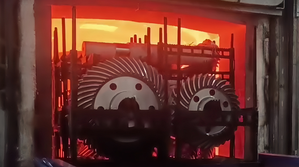
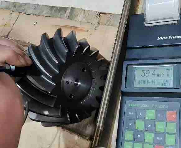
Operating conditions: Bears the entire machine weight, impact loads, and mud/water erosion. Requires carburized and quenched hardened tooth surfaces (e.g., 20CrMnTi), with contact fatigue strength ≥ 1800 MPa.
2. Swing / Slew Drive
The swing motor drives the spiral bevel gear set, converting the vertical shaft rotation into horizontal motion, enabling the upper turntable to rotate 360°.
Compared to the travel drive, the load is relatively steadier, but requires precise positioning and smooth, low-noise operation — precisely the advantage of the gradual meshing characteristic of spiral bevel gears.
3. Axle Drive Differential (if applicable — more common in wheeled excavators)
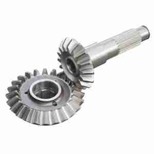
In the drive axle final drive of wheeled excavators, a spiral bevel gear set (drive pinion + driven ring gear) is used to achieve right-angle transmission and work together with the differential to distribute torque to the left and right wheels.
Track-type excavators typically do not have a differential, but some auxiliary-drive or transport models equipped with axles may also utilize this configuration.